Electronic device with optical heart rate monitor

An optical receiver, optical technology, applied in optical sensors, measuring pulse/heart rate, sensors, etc., can solve the problem of PPG signal signal-to-noise ratio reduction, inability to accurately determine the user's heart rate and pulse oxygen saturation, low optical signal electrical equality issues

Pending Publication Date: 2021-10-12
GARMIN
View PDF0 Cites 0 Cited by
  • Summary
  • Abstract
  • Description
  • Claims
  • Application Information

AI Technical Summary

Problems solved by technology

In this case, the optical transmitter and/or optical receiver may become detached from the user's skin - resulting in lower optical signal levels and reduced sig

Method used


Image

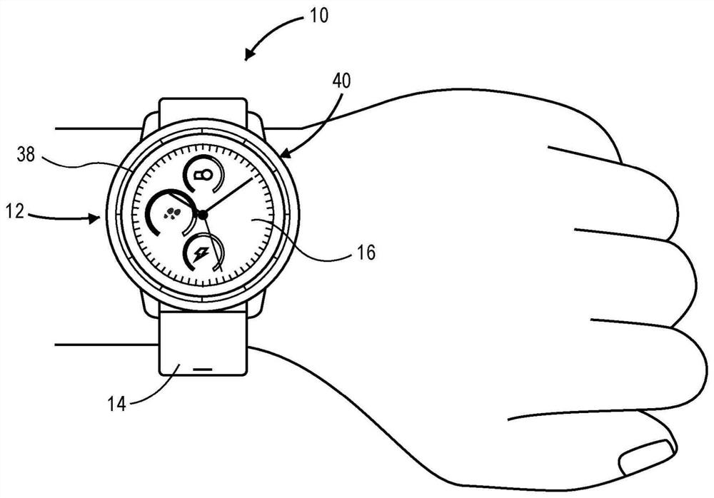
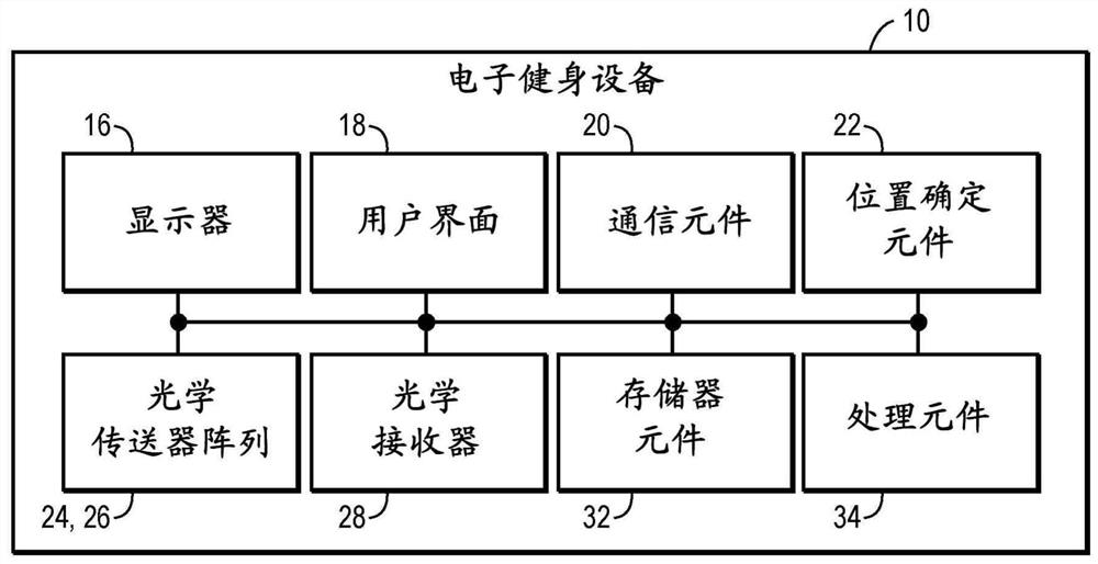
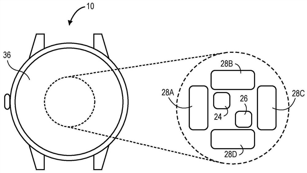
  • Electronic device with optical heart rate monitor
  • Electronic device with optical heart rate monitor
  • Electronic device with optical heart rate monitor

Examples


Embodiment Construction

[0021] The following detailed description of the technology refers to the accompanying drawings that illustrate specific embodiments in which the technology may be practiced. The examples are intended to describe aspects of the technology in sufficient detail to enable those skilled in the art to practice the technology. Other embodiments may be utilized and changes may be suggested without departing from the scope of the technology. Accordingly, the following detailed description is not made in a limiting sense. The scope of the technology is to be limited only by the appended claims, along with the full scope of equivalents to which such claims are entitled.

[0022] In this specification, reference to "one embodiment," "an embodiment" or "embodiments" means that the referenced feature or features are included in at least one embodiment of the technology. Individual references to "one embodiment," "an embodiment" or "embodiments" in this specification do not necessarily re...


PUM


Abstract

An electronic fitness device comprises a housing, a first optical transmitter array, a first optical receiver, and a second optical receiver. The first optical transmitter array is positioned at a first location on a bottom wall and may output a plurality of optical signals that pass through a user' s skin. The first optical receiver is positioned at a second location and may receive the optical signals from the first optical transmitter array such that the optical signals travel along a first signal path and a first distance. The second optical receiver is positioned at a third location and may receive the optical signals from the first optical transmitter array such that the optical signals travel along a second signal path and a second distance, wherein the second signal path is roughly orthogonal to the first signal path and the second distance is different from the first distance.

Description

[0001] (related application) [0002] This patent application claims priority under 35 U.S.C. § 119(e) to U.S. Provisional Patent Application Serial No. 62 / 819992, filed March 18, 2019, and titled "Improved Optical Cardiac Monitor" , which is hereby incorporated by reference in its entirety. Background technique [0003] The electronic fitness device may provide optical heart monitoring of the user of the device. A user may wear the electronic device such that the housing of the electronic device is positioned in contact with the user's skin - typically worn on the user's wrist. Cardiac monitoring may include physiological indicators and information such as the user's heart rate and pulse oximetry. The electronic fitness device may include optical devices such as optical transmitters that transmit optical signals into the user's skin and receive transmission or reflection of the optical signals from the skin and generate a photoplethysmogram (PPG) signal corresponding to the...

Claims


Application Information

Patent Timeline
IPC IPC(8): A61B5/024A61B5/00A61B5/1455
CPCA61B5/02427A61B5/14552A61B5/681A61B2562/046A61B5/02433A61B5/02438A61B2562/0238
Inventor S·利弗兰考斯P·R·麦克唐纳德K·A·史蒂文斯
Owner GARMIN
Why Eureka
Try Eureka