Supercharge Your Innovation With Domain-Expert AI Agents!

Liquid storage container

A technology for liquid containing containers and liquids, used in printing and other directions

Pending Publication Date: 2021-10-22
SEIKO EPSON CORP
View PDF1 Cites 0 Cited by
  • Summary
  • Abstract
  • Description
  • Claims
  • Application Information

AI Technical Summary

Problems solved by technology

As a result, there is a possibility that liquid containing air bubbles is supplied to the liquid consuming device

Method used


Image

  • Liquid storage container
  • Liquid storage container
  • Liquid storage container

Examples


no. 1 approach

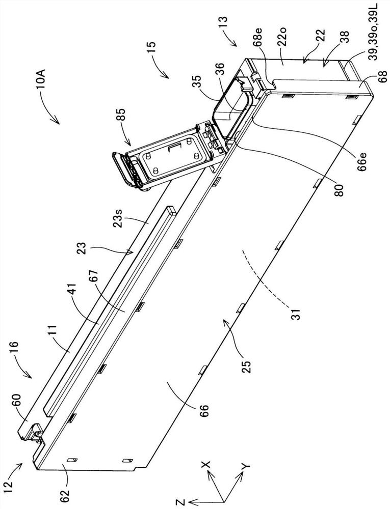
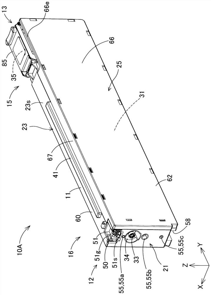
[0033] In accordance with reference figure 1 Note After the structure of the liquid consumption device 500 of the liquid receiving container 10a having the first embodiment is, reference Figure 2 ~ 22 Describe the structure of the liquid accommodating container 10a of the first embodiment.

[0034] A1. Structure of the liquid consumption device:

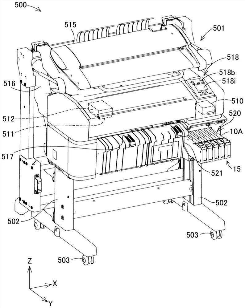
[0035] figure 1 It is a brief perspective view showing the structure of the liquid consumption device 500. exist figure 1 In the three directions of the three directions orthogonal, it illustrates the arrows X, Y, Z. In addition, in other various drawings referred to in this specification, arrows x, y, and z are also corresponding to figure 1 That is shown appropriately.

[0036]The direction of arrow x, y, and z corresponds to the configuration attitude of the liquid consumption device 500 in the usual use state. The "usual use state" means that the liquid consumption device 500 is configured on the horizontal plane. Hereinafter, the p...

no. 2 approach

[0126] In the liquid receiving container 10b of the second embodiment, the cross-sectional shape of the flow path of the first communication opening 76a is different from the liquid accommodating container 10a of the first embodiment. Other aspects are the same as the liquid accommodating container 10A of the first embodiment.

[0127] Figure 18 The top view of the first communication chamber 31 is viewed from the accommodating chamber 31 in the liquid receiving container 10b of the second embodiment. In the second embodiment, the first communication port 76a has an opening OP2 in the accommodating chamber 31.

[0128] The shape of the opening OP2 in the accommodating chamber 31 of the first communication section 76a is an ellipse. The shape of the opening OP2 is in the X direction as the longitudinal direction DL2, in the shape of the Y direction as the short side direction.

[0129] In the present embodiment, the shape of the opening OP2 in the receiving chamber 31 in the recei...

no. 3 approach

[0136] In the liquid receiving container 10c of the third embodiment, the cross-sectional shape of the flow path of the first communication opening 76a is different from the liquid accommodating container 10a of the first embodiment. Other aspects are the same as the liquid accommodating container 10A of the first embodiment.

[0137] Figure 19 A top view of the first communication chamber 31 is viewed from the -z direction from the accommodating chamber 31 in the liquid receiving container 10c of the third embodiment. In the third embodiment, the first communication opening 76a has an opening OP3 in the accommodating chamber 31.

[0138] The shape of the opening OP3 in the accommodating chamber 31 is the same as the center of gravity of the same shape, and the respective longitudes overlap the relative positions perpendicular to each other, that is, the so-called cross shape. The shape of the opening OP3 is the shape of the vertices of each rectangle in the same circle. As a res...


PUM


Abstract

The present invention relates to a liquid storage container in which it is difficult for air to be introduced into a filter chamber. The liquid storage container includes a storage chamber that stores a liquid, a filter chamber that is provided with a filter and receives the liquid from the storage chamber to filter the liquid by the filter, and a partition wall that separates the storage chamber and the filter chamber. The partition wall is provided with a communication hole structure that allows the storage chamber and the filter chamber to communicate with each other. A shape of one or more openings of the communication hole structure in the storage chamber is a shape in which a distance from a center of gravity of an entirety of the one or more openings to the closest point in a contour defining the one or more openings is smaller than a radius of a circle having the same area as an area of the entirety of the one or more openings.

Description

Technical field [0001] The present invention relates to a liquid accommodating container. Background technique [0002] Conventionally, there is a liquid accommodating container that houses a liquid supplied to a liquid consumption device such as an inkjet printer. The liquid receiving container of Patent Document 1 includes a receiving chamber accommodating a liquid, and a filter chamber removed from the liquid to the liquid contained in the liquid. The filter chamber is disposed below the accommodation room. The filter chamber is connected to the accommodating chamber via the first communication room provided at the bottom surface of the accommodating chamber. The liquid accommodating the liquid uses gravity to flow into the filter chamber via the first communication opening. The liquid is supplied from the filter chamber and supplied to the liquid consumption device. By providing such a structure, the liquid is supplied to the liquid consumption device after being removed from...

Claims


Application Information

Patent Timeline
Patent Type & Authority Applications(China)
IPC IPC(8): B41J2/175
CPCB41J2/17506B41J2/17563B41J2/17503B41J2/17513B41J2/17553B41J2/17523B41J2/17546B41J2/1753
Inventor 内藤直树唐泽政弘
Owner SEIKO EPSON CORP
Features
  • R&D
  • Intellectual Property
  • Life Sciences
  • Materials
  • Tech Scout
  • Unparalleled Data Quality
  • Higher Quality Content
  • 60% Fewer Hallucinations
Learn More