Grain drying and dehumidifying heat pump unit and grain drying circulation heat pump system

A grain drying and heat pump system technology, applied in grain drying, drying solid materials, non-progressive dryers, etc., can solve the problems of poor hot air drying efficiency, low hot air utilization rate, high labor intensity of workers, and achieve fast push efficiency. , The effect of reducing labor intensity and improving drying efficiency

Pending Publication Date: 2021-11-19
安徽齐品农业发展有限公司
View PDF8 Cites 0 Cited by
  • Summary
  • Abstract
  • Description
  • Claims
  • Application Information

AI Technical Summary

Problems solved by technology

[0005] Therefore, the present invention provides a grain drying dehumidification heat pump unit and a grain drying circulation heat pump system, through the drying dehumidification mechanism and the circulation preheating mechanism, to solve the serious pollution of combustion flue gas in grain processing, poor production environment, and high labor intensity of workers. At the same time, in the drying process, the traditional heat pump machine pushes the hot air slowly, the hot air drying efficiency is poor, and it does not have the advantage of energy saving, resulting in the problem of low utilization rate of hot air

Method used


Image

  • Grain drying and dehumidifying heat pump unit and grain drying circulation heat pump system
  • Grain drying and dehumidifying heat pump unit and grain drying circulation heat pump system
  • Grain drying and dehumidifying heat pump unit and grain drying circulation heat pump system

Examples


Embodiment Construction

[0031] The preferred embodiments of the present invention will be described below in conjunction with the accompanying drawings. It should be understood that the preferred embodiments described here are only used to illustrate and explain the present invention, and are not intended to limit the present invention.

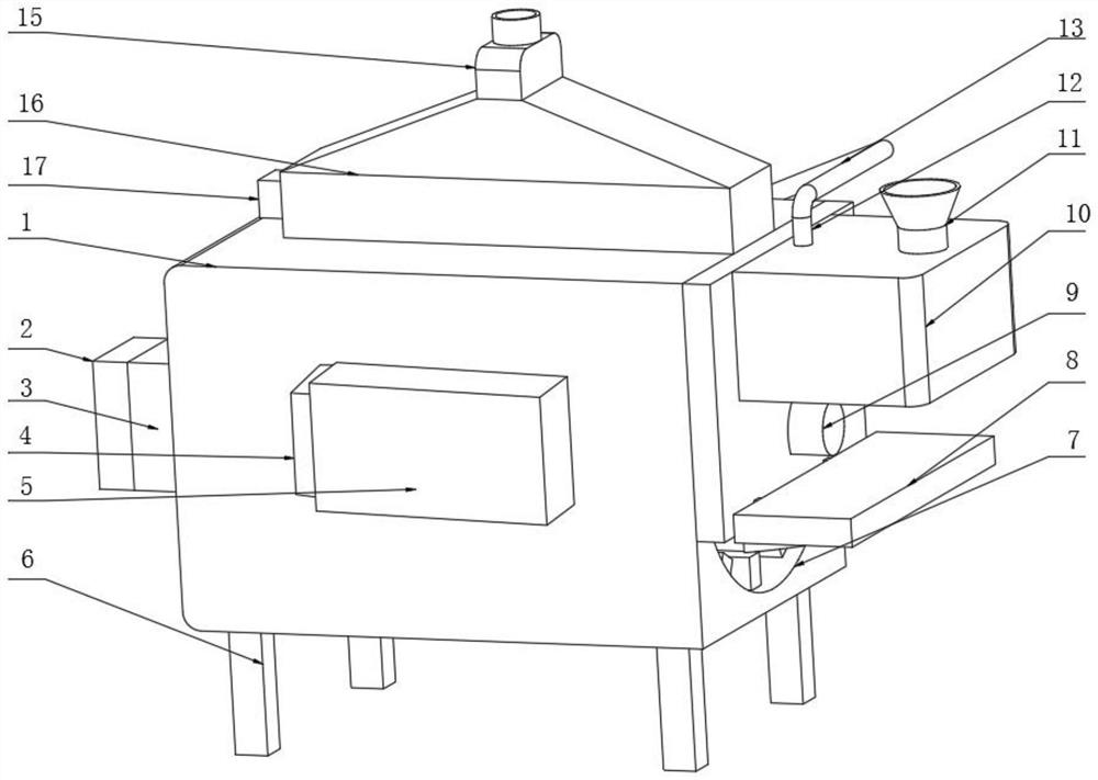
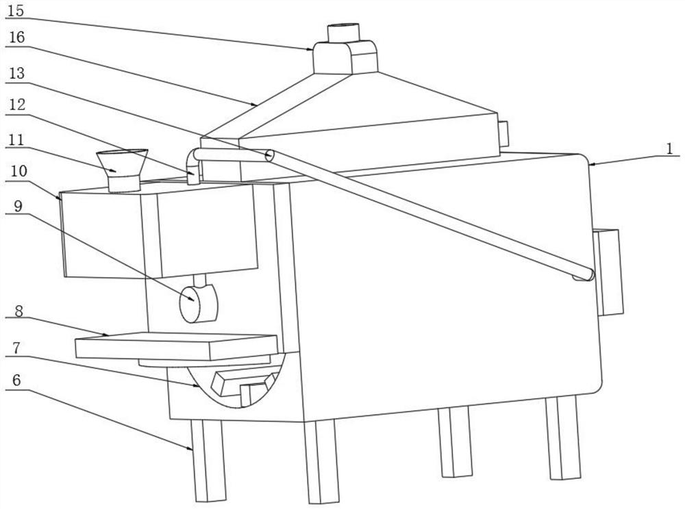
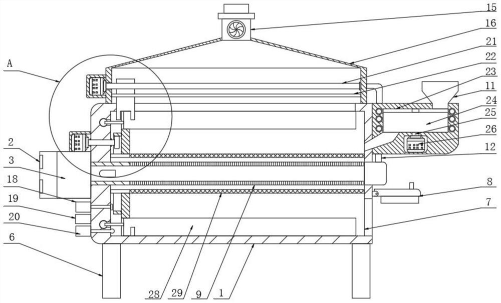
[0032] Refer to attached Figure 1-9 , a grain drying dehumidification heat pump unit and a grain drying circulation heat pump system provided by the present invention include a drying chamber 1, a drying chamber 7 is opened inside the drying chamber 1, and a drying and dehumidifying mechanism is arranged inside the drying chamber 7. One side of the drying chamber 1 is equipped with a circulation preheating mechanism;

[0033] The drying and dehumidifying mechanism includes an exhaust pipe 9, the exhaust pipe 9 is located inside the drying chamber 7, both ends of the exhaust pipe 9 run through the drying chamber 1, and the outside of the exhaust pipe 9 is provided w...


PUM


Abstract

The invention discloses a grain drying and dehumidifying heat pump unit and a grain drying circulation heat pump system. According to the technical scheme, the grain drying and dehumidifying heat pump unit and the grain drying circulation heat pump system comprise a drying chamber, a drying cavity is formed in the interior of the drying chamber, a drying and dehumidifying mechanism is arranged in the interior of the drying cavity, a circulation preheating mechanism is arranged on one side of the drying chamber, the drying and dehumidifying mechanism comprises an exhaust pipe, the exhaust pipe is arranged in the interior of the drying cavity, the two ends of the exhaust pipe both penetrate through the drying chamber, the exterior of the exhaust pipe is provided with a material blocking cover plate in a sleeved mode, the two ends of the material blocking cover plate are fixedly connected with the side wall of the drying cavity, the exterior of the material blocking cover plate is provided with a disc in a sleeved mode, and one side of the disc is fixedly connected with an annular inner gear. The grain drying and dehumidifying heat pump unit and the grain drying circulation heat pump system have the beneficial effects that the influence and pollution to the environment during grain drying are reduced, the labor intensity during grain drying is reduced, the automation degree of the drying process is improved, meanwhile, the hot air pushing efficiency is high, the drying efficiency is high, hot air circulation conveying is achieved, the hot air utilization rate is improved, and energy conservation and environment protection are achieved.

Description

technical field [0001] The invention relates to the field of drying and dehumidification equipment, in particular to a grain drying and dehumidifying heat pump unit and a grain drying circulation heat pump system. Background technique [0002] The grain drying method is to give the grain a certain form of energy through the drying medium, so that part of the moisture in the grain will be vaporized and overflowed. The basic condition for realizing the drying process is to have energy transfer, transformation and consumption, and use heating gas (furnace gas, hot air) Direct contact with the grain, the heat is transferred to the grain by convection, so that part of the moisture in the grain is vaporized, so as to achieve the purpose of drying. The vaporized moisture is taken away, so the drying medium acts as a heat carrier and a mixture. The convection dry coal method is the most widely used in grain drying technology, and the convection heat transfer grain dryer is also the ...

Claims


Application Information

Patent Timeline
Patent Type & Authority Applications(China)
IPC IPC(8): F26B11/16F26B21/08F26B21/10F26B25/04F26B25/06F25B30/02A23B9/08
CPCF26B11/16F26B21/001F26B21/004F26B21/08F26B21/10F26B25/04F26B25/06F25B30/02A23B9/08F26B2200/06Y02A40/90Y02P60/85
Inventor 姚弟峰康盼丽汪格
Owner 安徽齐品农业发展有限公司
Why Eureka
Try Eureka