

Water inlet valve pipe and water control valve
A technology for water inlet pipes and water inlet valves, which is applied in water supply devices, flushing equipment with water tanks, buildings, etc., can solve the problems of inconsistent and embarrassing length requirements of water inlet valve pipes, achieve remarkable practical effects and improve the scope of application Effect
- Summary
- Abstract
- Description
- Claims
- Application Information
AI Technical Summary
Problems solved by technology
Method used
Image

Examples
Embodiment Construction
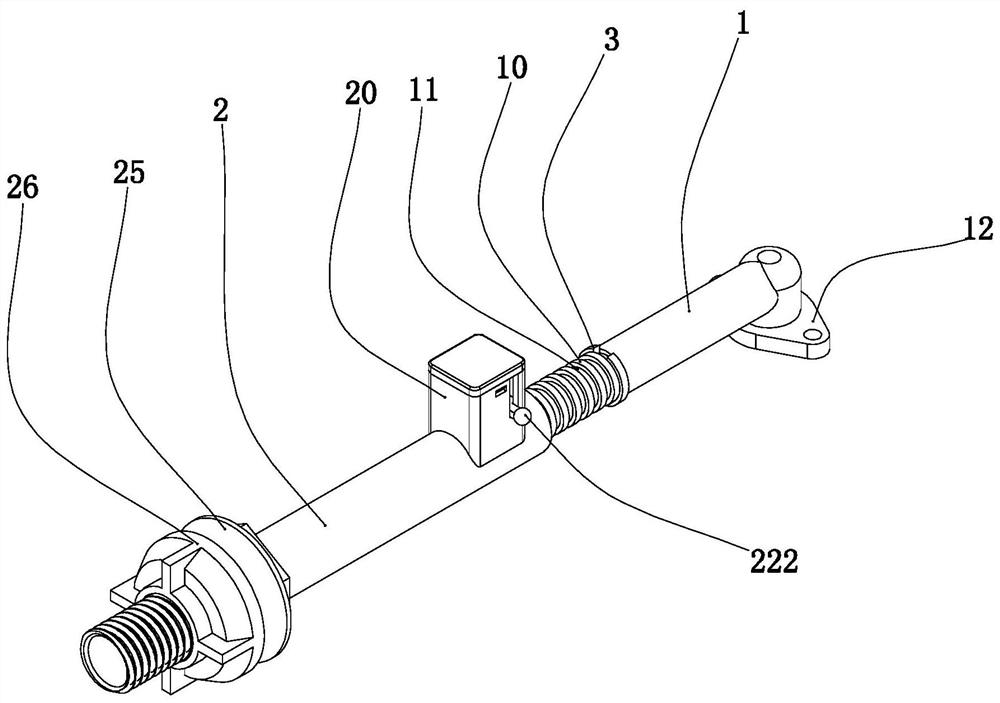
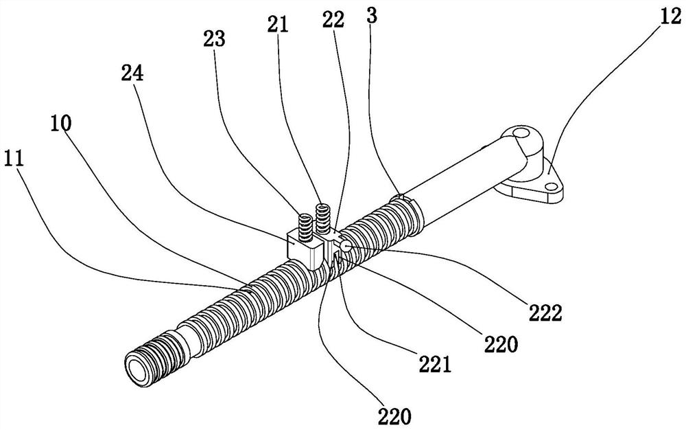
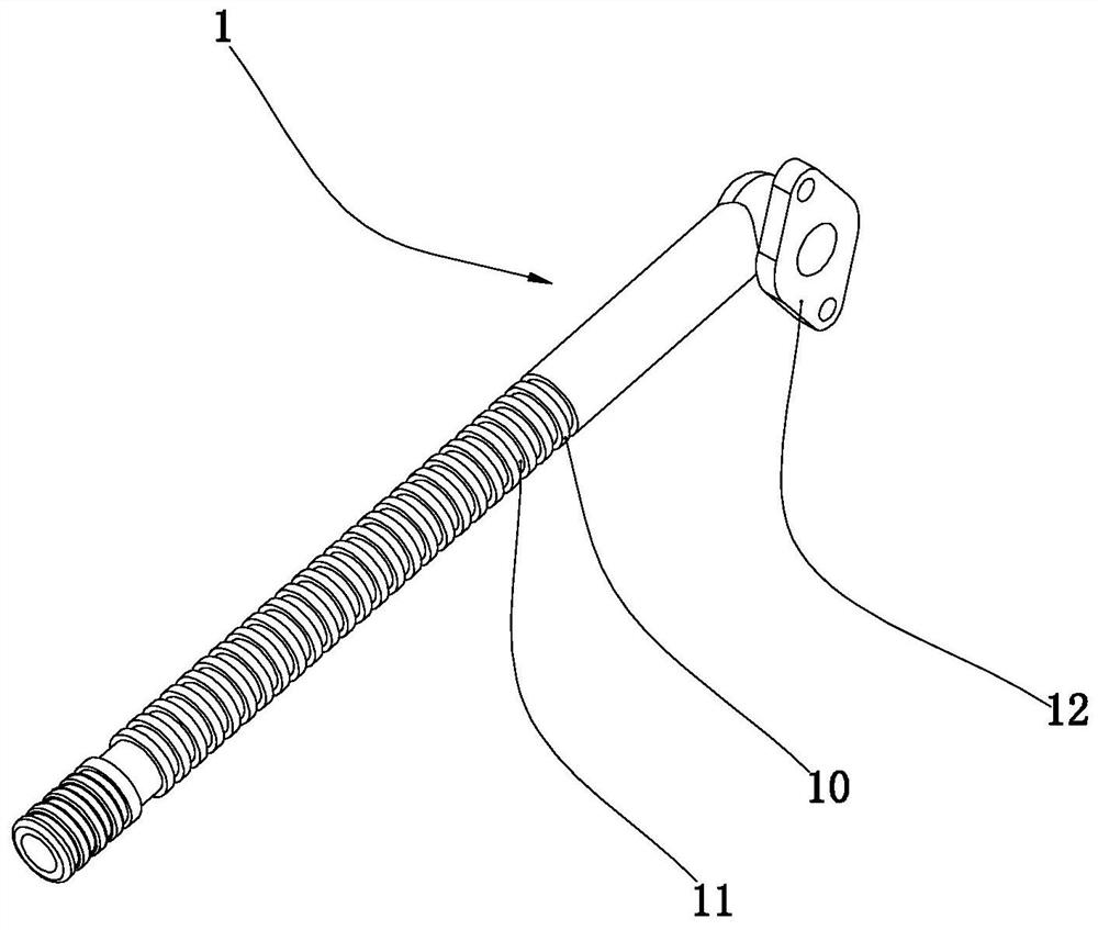
[0023] Figure 1-Figure 7 Shown, this embodiment adopts a water inlet valve pipe, wherein figure 1 combine figure 2 Obviously, the water inlet valve tube of this embodiment includes
[0024] Water inlet pipe 1: a number of positioning protruding rings 10 distributed in an axial array are formed on its outer surface, and positioning card slots 11 are formed between every two adjacent positioning protruding rings 10. In the prior art, the outer surface of part of the water inlet pipe Several positioning slots 11 are also arranged on the surface, but the positioning slots 11 of this structure are specially used for setting rubber sealing rings to prevent water leakage;
[0025] Outer pipe 2: It is sleeved on the water inlet pipe 1, and a radially extending installation shell 20 is formed on it, from which Figure 4 with Figure 5 It can be seen that the outer tube 2 also includes an elastic buffer pad 25 and a movable nut 26 installed at its lower end position, and the inner...
PUM
 Abstract
Description
Claims
Application Information