Deep building pit trussed-beam inner support integral application pre-stress method

A truss-type, prestressed technology, applied in the engineering field, can solve the problems of small influence range (generally about 5-6m, poor integrity of prestressing, inability to apply prestressing, etc.), and achieves wide application range, long installation time, The effect of large compression deformation

Inactive Publication Date: 2008-09-03
CHINA FIRST METALLURGICAL GROUP
View PDF0 Cites 32 Cited by
  • Summary
  • Abstract
  • Description
  • Claims
  • Application Information

AI Technical Summary

Problems solved by technology

Therefore, the method of applying prestress to the top support by a single rod has a small scope of application (the width of the foundation pit is about 20m), the applied prestress is small, and the influence range of the applied prestress on the foundation pit is small (ge

Method used


Image

  • Deep building pit trussed-beam inner support integral application pre-stress method
  • Deep building pit trussed-beam inner support integral application pre-stress method
  • Deep building pit trussed-beam inner support integral application pre-stress method

Examples


Example Embodiment

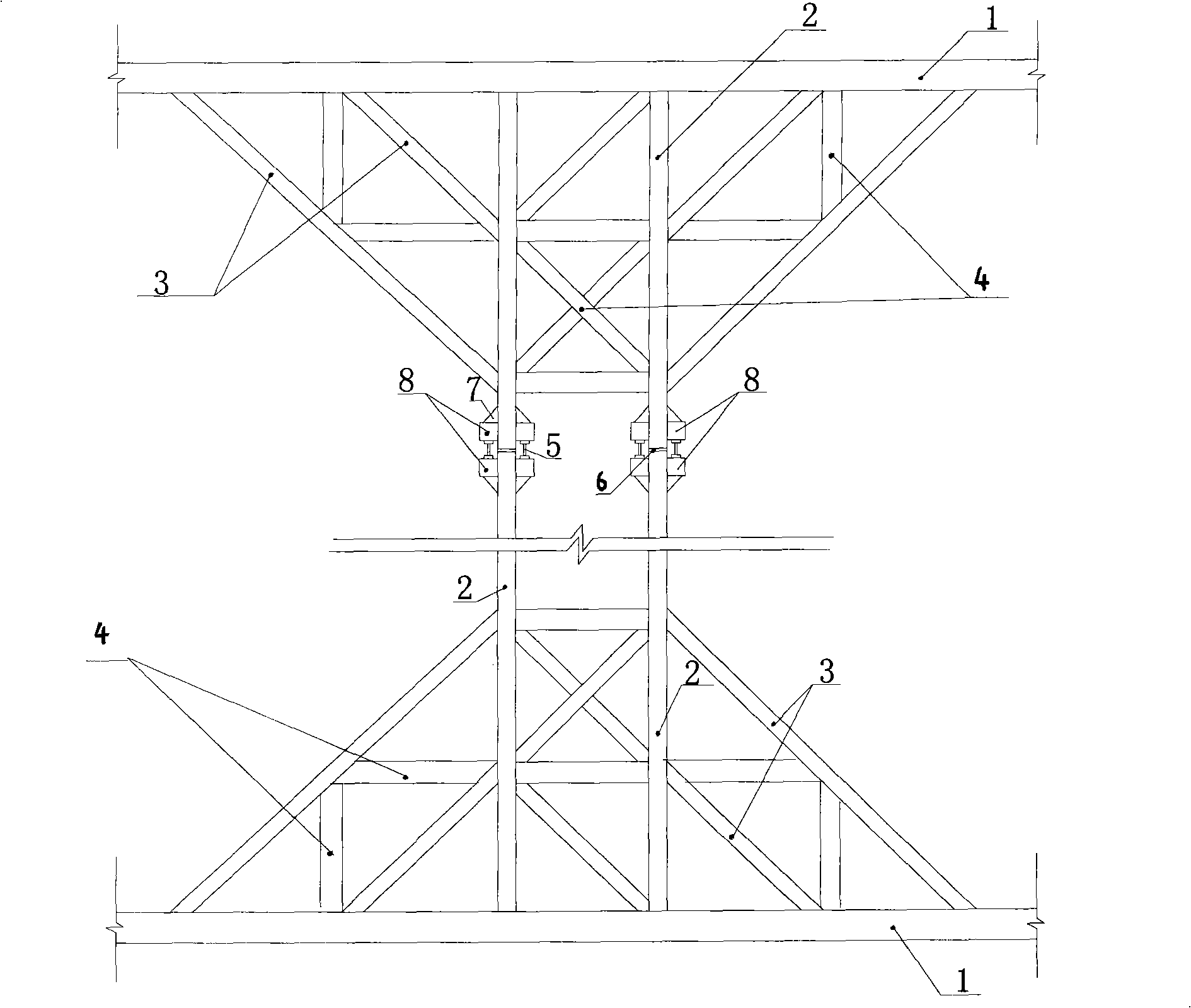
[0032] Embodiment 1: see figure 1 . This embodiment includes the following steps: (1) install the crown beam or waist beam 1 in the deep foundation pit, install the main top strut 2, the diagonal bar 3 and the web bar 4 to form a truss-type internal support, and install the above-mentioned truss-type internal support Installed between two opposite pit walls in the deep foundation pit; (2) On each main top strut 2, a prestressed force transmission seat is installed along the axial direction of the main top strut 2, and the prestressed force transmission seat It is composed of corbels 8 and stiffeners 7 welded on both sides of the main top strut 2; (3) a jack 5 or Jack group, and apply a certain prestress first or not apply prestress first, apply a certain prestress first to avoid the phenomenon of sudden increase in deformation after cutting off the main top strut; (4) Cut off each main top strut The main top strut 2 between the corbels 8 on both sides is prestressed with the...

Example Embodiment

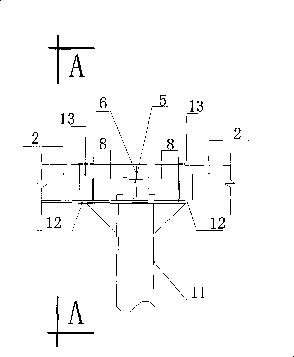
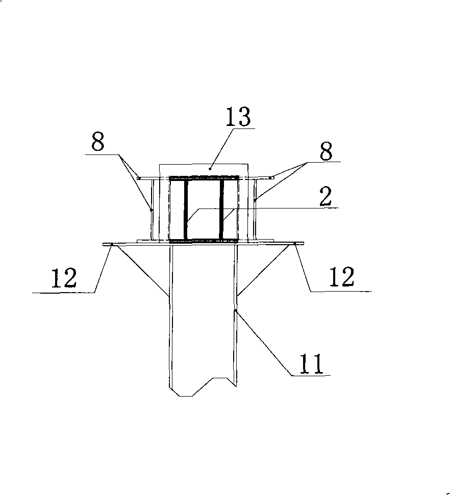
[0033] Example 2: see figure 1 , figure 2 and image 3. The steps of this embodiment are basically the same as those of Embodiment 1, the difference being that for a foundation pit with a large span, it is necessary to install the truss-type internal support described in step (1) of Embodiment 1 before connecting with each main support. Set the column 11 fixed in the column pile below the bottom surface of the deep foundation pit at the corresponding place where the jack is installed on the pole 2, set the tray 12 on the upper end of the column 11, the tray 12 and the column 11 are welded firmly, and set the fixture 13 at each column tray Before the overall prestressing of the truss-type inner support in Embodiment 1, the main top struts 2 at both ends of the jack 5 are respectively fixed on the pallet 12 with the fixture 13, so as to prevent the truss-type inner support from bulging upwards.

Example Embodiment

[0034] Embodiment 3: see figure 1 and Figure 4 , this embodiment is realized on the basis of embodiment 1 or embodiment 2, and its steps are basically the same as embodiment 1 or embodiment 2, the difference is that two or more roots in the above two embodiments Corbels 9 are arranged at the connection between the main top brace 2 and the crown beam or waist beam 1, and the corbel 9 is welded to the crown beam or waist beam 1 or the vertical structure 14 of the foundation pit. Two or more main top braces 2 The ends are respectively placed on the corbels 9, and a gap 10 of about 1 cm is maintained with the crown beam or the waist beam 1. The purpose is to ensure that the two or four oblique rods 3 are stressed first and gradually increased when the prestress is applied. , and then according to the size of the force monitoring results at these two or four inclined bars 3 places, determine the timing of closing the gap between two or more main top struts 2 and the crown beam or...


PUM


Abstract

The present invention relates to a method for wholly exerting pre-stress to the trussed internal bearing in the deep foundation pitch. The method comprises the following steps: installing an internal bearing which is composed of a principal top brace, a diagonal rod and a web rod or composed of a principal top brace and a web rod, and installing the trussed internal bearing between two pit walls of the deep foundation pitches; (2) installing a pre-stress force-transferring seat along the axial direction of the principal top brace on each principal top brace; (3) arranging a jack along the axial direction between two pre-stress force-transferring seats of each principal top brace; and (4) cutting off the principal top brace between two force-transferring seats of each principal top brace, exerting pre-stress with the jack, and when the pre-stress which should be exerted is obtained, reinforcing and welding the gap which is between the fracture surface of the cut principal top brace and is generated by exerting pre-stress with the steel material. The method has the advantages of quick installation, short time period for exerting pre-stress, being able to counteracting the compressing deformation of the member bar, and being able to quickly and effectively control the deformation in the deep foundation pitch.

Description

technical field [0001] The invention relates to engineering fields such as civil engineering and construction, and municipal engineering, and in particular relates to a method for integrally applying prestress to a truss-type inner support of a deep foundation pit. Background technique [0002] At present, in the design and construction of support in deep foundation pits, over-prestressing is applied to a single bar in the case of a single-bar-to-top-brace arrangement, and only a single steel structure is over-prestressed to the top-brace. The direction of the pole and the axis of the support member on the top are on a straight line, and the single prestress applied is small. The single support on the top of the single pole is suitable for the foundation pit whose width is not wide (such as about 20m wide); but when the width of the foundation pit If it is wider, a single rod cannot be used as the inner support of the roof. At this time, in most cases, a truss-type inner sup...

Claims


Application Information

Patent Timeline
IPC IPC(8): E02D17/04
Inventor 王平
Owner CHINA FIRST METALLURGICAL GROUP
Why Eureka
Try Eureka