X-ray moving image display device and X-ray moving image display method

A technology of dynamic images and display devices, applied in image communication, instruments for radiological diagnosis, medical science, etc. Medical and other issues to achieve effective medical results

Pending Publication Date: 2022-03-15
KONICA MINOLTA INC
View PDF1 Cites 0 Cited by
  • Summary
  • Abstract
  • Description
  • Claims
  • Application Information

AI Technical Summary

Problems solved by technology

[0010] However, explanations and evaluations of rehabilitation methods are mostly subjective, and rely on the skills of physical therapists. Moreover, rehabilitation subjects cannot objectively grasp the effects of their own rehabilitation, and it is difficult to maintain enthusiasm for rehabilitation. Subjects are provided with effective medical care
[0011] In Patent Document 1, the X-ray image is superimposed on the image of the camera. However, in order to efficiently perform positioning at the time of X-ray imaging, even if a doctor or a physical therapist observes the image, it is impossible to simultaneously evaluate the movement of the body on the surface and inside the body. The activities of the internal organs, etc., cannot provide effective medical treatment for patients

Method used


Image

  • X-ray moving image display device and X-ray moving image display method
  • X-ray moving image display device and X-ray moving image display method
  • X-ray moving image display device and X-ray moving image display method

Examples


no. 1 approach >

[0072] [Structure of Moving Image Display System 100 ]

[0073] First, the structure in the first embodiment of the present invention will be described.

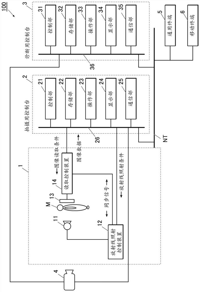
[0074] exist figure 1 The overall structure of the video display system 100 in this embodiment is shown.

[0075] Such as figure 1 As shown, the dynamic image display system 100 is configured such that the imaging device 1 and the camera 4 are connected to the imaging console 2 through a communication cable or the like, and the imaging console 2, the diagnostic console 3, the general-purpose terminal 5, and the mobile terminal 6 can be connected via Communication network NT connection such as LAN (Local Area Network: local area network). Among the devices constituting the moving image display system 100, the imaging device 1, the imaging console 2, and the diagnostic console 3 conform to the DICOM (Digital Image and Communications in Medicine) standard, and communication among these devices is based on DICOM is performed...

no. 2 approach >

[0160] Hereinafter, a second embodiment of the present invention will be described.

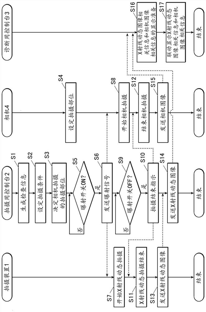
[0161] In the first embodiment, the case where X-ray dynamic imaging and camera imaging start when the exposure switch is pressed (ON) and end X-ray dynamic imaging and camera imaging when the exposure switch is released (OFF) is taken as an example. The description has been made, but in the second embodiment, a case where a camera switch for instructing the camera 4 to shoot is provided separately from the exposure switch will be described as an example.

[0162] That is, in the second embodiment, a camera switch is connected to the camera 4 . In this embodiment, the camera switch is arranged near the exposure switch, and the person performing the photography can simultaneously press the exposure switch and the camera switch.

[0163] The other configurations of the moving image display system 100 are the same as those described in the first embodiment, so the description will be referred t...

no. 3 approach >

[0185] Hereinafter, a third embodiment of the present invention will be described.

[0186] In the first and second embodiments, the case where X-ray dynamic imaging and camera imaging are performed in conjunction with each other to acquire X-ray dynamic images and camera images in the same period has been described as an example. However, in the third embodiment, An example in which the console 3 for diagnosis is controlled to specify and display an X-ray moving image and a camera image captured in the same period will be described as an example.


PUM


Abstract

The invention provides an X-ray moving image display device and an X-ray moving image display method capable of providing effective medical treatment for a patient. A control unit of a diagnostic console acquires X-ray moving image-related information relating to an X-ray moving image obtained by X-ray moving imaging, and camera image-related information relating to a camera image obtained by camera imaging. The acquired X-ray moving image-related information and the camera image-related information are displayed on a display unit in conjunction with each other.

Description

technical field [0001] The present invention relates to an X-ray dynamic image display device, a program, an X-ray dynamic image display method and an X-ray dynamic image display system. Background technique [0002] Conventionally, in the medical field, image diagnosis such as an X-ray image obtained by imaging a site of interest, an X-ray moving image, or the like is performed. Also, for example, Patent Document 1 describes that a subject is imaged with a video camera during X-ray imaging, and an X-ray image is displayed superimposed on the obtained image. [0003] 【Prior technical literature】 [0004] 【Patent Literature】 [0005] Patent Document 1: Japanese Patent Laid-Open No. 2016-34300 [0006] However, when a clinician makes a diagnosis such as breathing, not only image diagnosis, but also face-to-face consultation, visual and palpation, etc. observe facial expressions and body movements, and subjectively observe the effect of treatment for diagnosis. [0007] How...

Claims


Application Information

Patent Timeline
Patent Type & Authority Applications(China)
IPC IPC(8): A61B6/00
CPCA61B6/461A61B6/463A61B6/5247H04N5/262A61B6/487A61B6/5217A61B6/50A61B5/0077A61B5/7425G06T2207/10016G06T2207/30004G06T2207/30061G06V2201/03
Inventor 角森昭教
Owner KONICA MINOLTA INC
Why Eureka
Try Eureka