
High-speed ink-jet screen making machine

An inkjet, screen machine technology, applied in printing and other directions, can solve the problems of reduced moving speed, reduced inkjet accuracy, product manufacturing failure, etc., to prevent ink breakage and ensure inkjet accuracy.

Active Publication Date: 2022-04-08
SHAOXING XINCHANG PRINTING MACHINERY TECH CO LTD
View PDF15 Cites 0 Cited by
  • Summary
  • Abstract
  • Description
  • Claims
  • Application Information

AI Technical Summary

Problems solved by technology

[0002] In the prior art, the inkjet cartridge often only acts as a fixed inkjet tube or is used for an inkjet that is only connected to the inkjet tube during the inkjet process , the ink or toner is ejected through the inkjet tube for printing. Once the ink or toner supply device connected to the inkjet tube finishes spraying the ink or toner, it will directly cause the inkjet to not eject ink. The situation, that is, the ink cut-off status, there is no ink cut-off warning in the middle process and a buffer time is given for the staff to replenish ink or toner, which eventually leads to product failure and loss
[0003]In addition, during the inkjet process, the inkjet device moves back and forth on a horizontal bar continuously and performs inkjet work. Since the inkjet device has a certain weight, In the long-term use process, the crossbar is easy to bend the crossbar under the action of gravity. Once the crossbar is bent, the direction and position of the inkjet will change when the inkjet device moves through the bend. In addition, the inkjet device Sliding on the curved part will generate friction to reduce its moving speed, in summary, resulting in a decrease in the accuracy of inkjet

Method used


Image

  • High-speed ink-jet screen making machine
  • High-speed ink-jet screen making machine
  • High-speed ink-jet screen making machine

Examples


Embodiment Construction

[0030] The present invention will be described in further detail below in conjunction with the accompanying drawings and specific embodiments.

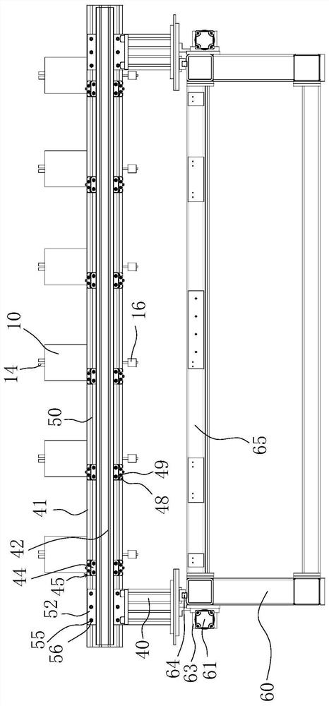
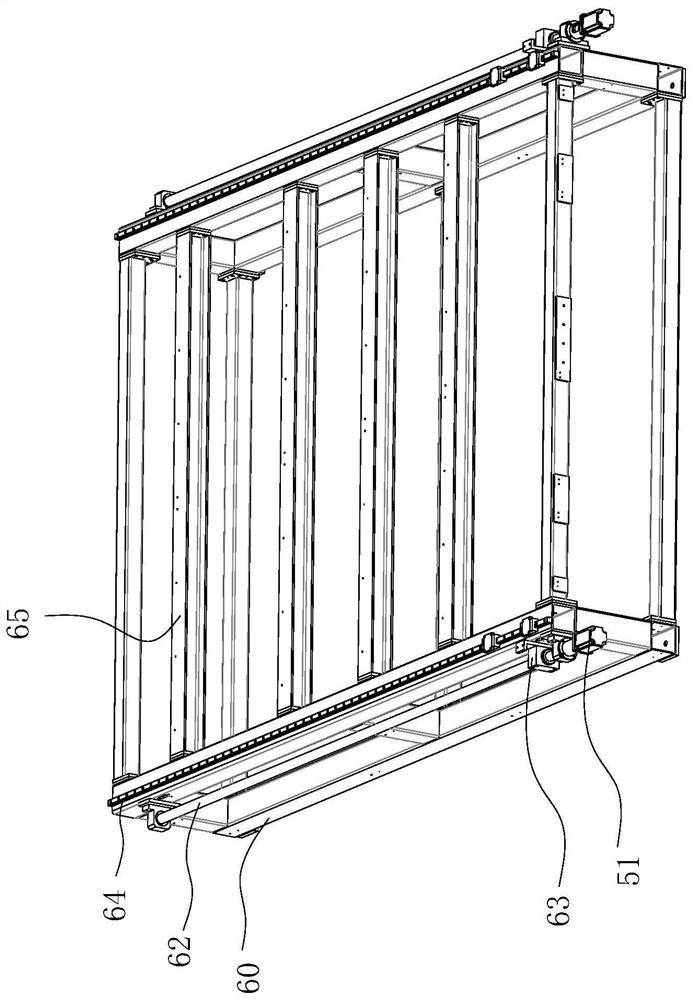
[0031] combine Figure 1-9 As shown, a high-speed inkjet type screen making machine includes a frame 60, two support blocks 40 are slidably connected to the frame 60, and a main beam 41 is erected on the two support blocks 40, and the two support blocks 40 There is a gap between the main beam 41 and the sub-beam 42 to form a sliding passage 43, and several sliding plates 44 are slidably connected in the sliding passage 43, and the sliding plates 44 and the auxiliary The beams 42 are slidably connected, and each sliding plate 44 is supported on the main beam 41 through a detachable clamping mechanism 45. Each sliding plate 44 is provided with an ink tank 10, and the ink tank 10 is provided with an ink tube 11. The inlet and outlet of the ink tube 11 extend out of the two ends of the ink tank 10 respectively, and the ink tank 10 is als...


PUM


Abstract

The invention provides a high-speed ink jet type screen making machine, and belongs to the field of ink jet. The device comprises a frame, two supporting blocks are connected to the frame in a sliding mode, a main beam is erected on the two supporting blocks, an auxiliary beam is further erected on the two supporting blocks, a gap is formed between the main beam and the auxiliary beam, a sliding channel is formed between the main beam and the auxiliary beam, a plurality of sliding plates are connected into the sliding channel in a sliding mode, and the sliding plates are connected with the auxiliary beam in a sliding mode. Each sliding plate is supported on the main beam through a detachable clamping mechanism, an ink box is arranged on each sliding plate, an ink pipe is arranged in each ink box in a penetrating mode, an inlet and an outlet of each ink pipe extend out of the two ends of the corresponding ink box respectively, a peristaltic pump component is further arranged in each ink box, and each ink pipe penetrates through the corresponding peristaltic pump component. A buffering ink box arranged on the ink pipe is arranged above the peristaltic pump component.

Description

technical field [0001] The invention belongs to the field of inkjet, in particular to a high-speed inkjet screen making machine. Background technique [0002] In the prior art, the inkjet box often only acts as a fixed inkjet tube or is used to only be provided with an inkjet connected to the inkjet tube during the inkjet process, and the ink or toner passes through the inkjet tube between the inkjet tubes Once the ink or toner supply device connected to the inkjet tube finishes spraying the ink or toner, it will directly lead to the situation that the inkjet does not eject ink, that is, the ink is cut off. There is no ink cutoff warning and a The buffer time is for the staff to replenish ink or toner, which eventually leads to product failure and loss. [0003] In addition, during the ink-jet process, the ink-jet device moves back and forth on a horizontal bar to carry out the ink-jet work. Since the ink-jet device has a certain weight, the horizontal bar is easy to use un...

Claims


Application Information

Patent Timeline
Patent Type & Authority Applications(China)
IPC IPC(8): B41J2/175
Inventor 傅建国
Owner SHAOXING XINCHANG PRINTING MACHINERY TECH CO LTD
Learn More