Layered superposition array optical waveguide and head-mounted device

An array optical waveguide and head-mounted device technology, applied in the field of optical waveguides, can solve the problems of reducing brightness uniformity and clarity, and achieve the effect of reducing the interference of display effects, reducing differences, and improving user experience.

Inactive Publication Date: 2022-07-22
BEIJING LLVISION TECH CO LTD
View PDF9 Cites 0 Cited by
  • Summary
  • Abstract
  • Description
  • Claims
  • Application Information

AI Technical Summary

Problems solved by technology

[0006] The present invention provides a layered superimposed array optical waveguide and a head-mounted device, which is used to solve the problem that the array optical waveguide in the prior art simply designs the reflectivity of the splitting surface according to the law of proportion, so that there are obvious bright and dark stripes in the displayed image, It reduces the brightness uniformity and clarity of the displayed image, can reduce the difference in the light intensity of the light reflected from different positions of the beam splitting surface of the same beam splitting prism module, and reduces the impact of bright and dark stripes on the image displayed by the array optical waveguide The interference of the display effect can be improved, the brightness uniformity and clarity of the image can be improved, and the user experience can be improved.

Method used


Image

  • Layered superposition array optical waveguide and head-mounted device
  • Layered superposition array optical waveguide and head-mounted device
  • Layered superposition array optical waveguide and head-mounted device

Examples


Embodiment Construction

[0025] In order to make the objectives, technical solutions and advantages of the present invention clearer, the technical solutions in the present invention will be clearly and completely described below with reference to the accompanying drawings. Obviously, the described embodiments are part of the embodiments of the present invention. , not all examples. Based on the embodiments of the present invention, all other embodiments obtained by those of ordinary skill in the art without creative efforts shall fall within the protection scope of the present invention.

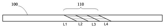
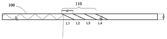
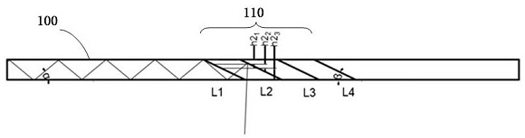
[0026] see figure 1 , figure 1 is a schematic diagram of the layered stack array optical waveguide provided by the present invention, such as figure 1 As shown, the present invention provides a layered and stacked array optical waveguide. A beam splitting prism array 110 is arranged in the light coupling out area of ​​the optical waveguide 100 , and the beam splitting prism array 110 includes at least two beam sp...


PUM

PropertyMeasurementUnit
reflectanceaaaaaaaaaa

Abstract

The invention provides a layered superposition array optical waveguide and a head-mounted device. Wherein a beam splitter prism array is arranged in a light coupling-out area of the optical waveguide, the beam splitter prism array comprises at least two beam splitter prism modules, beam splitting surfaces of the beam splitter prism modules are parallel and are arranged at a certain interval, and a certain inclination angle is formed between the beam splitting surfaces and the optical waveguide; each beam splitter prism module in the beam splitter prism array comprises at least one layer of beam splitter prisms, the beam splitter prisms in the beam splitter prism modules are overlaid and glued, beam splitting surfaces of the beam splitter prisms are connected to form beam splitting surfaces of the beam splitter prism modules, and the reflectivity of beam splitting film layers plated on the beam splitting surfaces of the beam splitter prisms is higher than that of the beam splitting prisms. Therefore, the power of the light reflected by each layer of beam splitter prism in the same beam splitter prism module is consistent. The interference of bright and dark fringes on the display effect of the image displayed by the array optical waveguide can be reduced, the brightness uniformity and definition of the image are improved, and the use experience of a user is improved.

Description

technical field [0001] The invention relates to the technical field of optical waveguides, in particular to a layered and stacked array optical waveguide and a head-mounted device. Background technique [0002] Augmented Reality (AR) technology is a technology that integrates virtual information with the real world. It has very broad application prospects in the fields of industrial and consumer electronics. The optical waveguide couples the light into the substrate through total reflection transmission and then couples the light out. It has the characteristics of thinness and high penetration of external light, which is more in line with the needs of consumer-grade AR devices, and has been widely used in AR devices in recent years. [0003] Arrayed optical waveguide is an optical component used in AR equipment that realizes light coupling and pupil dilation through a beam splitting prism array. The array optical waveguide is formed by gluing a plurality of beam-splitting p...

Claims


Application Information

Patent Timeline
Patent Type & Authority Applications(China)
IPC IPC(8): G02B27/01
CPCG02B27/0172
Inventor 赵满李勇吴斐梁祥龙李文江
Owner BEIJING LLVISION TECH CO LTD
Why Eureka
Try Eureka