Photo-alignment device, photo-alignment method of display substrate, and display substrate

A display substrate and photo-alignment technology, applied in optics, nonlinear optics, instruments, etc., can solve problems such as difficult adjustment of photo-orientation exposure uniformity

Inactive Publication Date: 2019-09-20
CHENGDU TIANMA MICROELECTRONICS
View PDF5 Cites 0 Cited by
  • Summary
  • Abstract
  • Description
  • Claims
  • Application Information

AI Technical Summary

Problems solved by technology

[0005] Embodiments of the present invention provide a photo-alignment device, a photo-alignment method for a display substrate, and a display substrate to solve the problem of difficult adjustment of photo-alignment exposure uniformity in the prior art

Method used


Image

  • Photo-alignment device, photo-alignment method of display substrate, and display substrate
  • Photo-alignment device, photo-alignment method of display substrate, and display substrate
  • Photo-alignment device, photo-alignment method of display substrate, and display substrate

Examples


Embodiment Construction

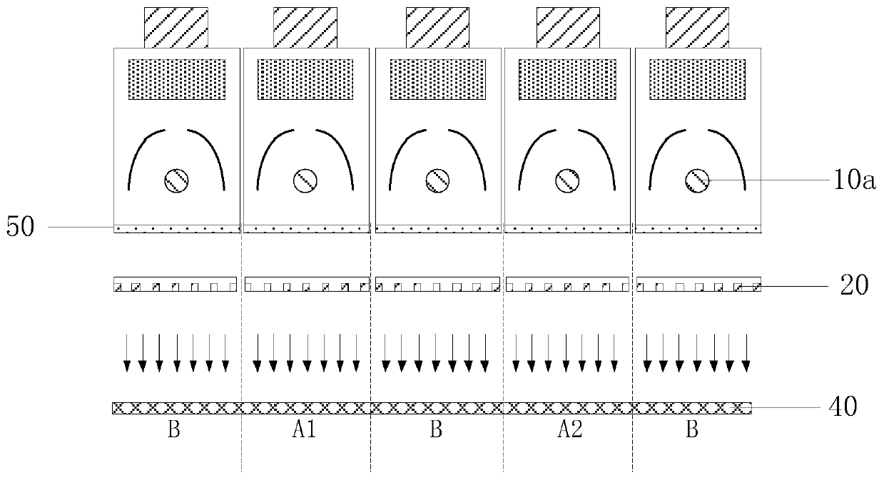
[0042] Light alignment devices are mainly divided into short lamp splicing devices and long lamp devices, among which, figure 1 It is a schematic structural diagram of a short lamp splicing device, such as figure 1 As shown, generally, each short lamp splicing device can include 30 to 100 short lamp ultraviolet light sources, figure 1 In the figure, five short-lamp UV light sources 10a are taken as an example. In order to adjust the uniformity of light orientation and exposure, the in-plane exposure is mainly adjusted by adjusting the power of the short-lamp UV light source 10a and increasing or decreasing the brightness of the short-lamp UV light source 10a alone. Uniformity.

[0043] However, due to the large number of short-lamp UV light sources in the short-lamp splicing device, the number of short-lamp UV light sources that need to be adjusted is large, the adjustment is difficult, and the adjustment cycle is frequent. In addition, because the short-lamp UV light source ...


PUM

PropertyMeasurementUnit
thicknessaaaaaaaaaa
thicknessaaaaaaaaaa

Abstract

The invention discloses a photo-alignment device, a photo-alignment method of a display substrate, and the display substrate. The photo-alignment device comprises ultraviolet light sources, polarizing wire grids and attenuation sheets which are arranged on the light-emitting sides of the ultraviolet light sources, a placing frame, and fixing components, wherein the attenuation sheets are detachably fixed onto the placing frame by means of the fixing components; the polarizing wire grids are configured to convert light emitted from the ultraviolet light sources into polarized light required for a photo-alignment process; a region covered by the light emitted from the ultraviolet light sources is divided into a first region and a second region; the intensity of the light emitted to the first region from the ultraviolet light sources is higher than that of the light emitted to the second region; and the attenuation sheets are positioned in the first region, and are used for weakening the light intensity of light rays emitted from the ultraviolet light sources. By arranging the attenuation sheets in the first region, the exposure uniformity of photo-alignment is improved, and the attenuation sheets are detachably fixed on the placing frame by means of the fixing components, thereby facilitating the pick-and-place of the attenuation sheets and adjustment of the number of the attenuating sheets.

Description

technical field [0001] The invention relates to the field of display technology, in particular to a photo-alignment device, a photo-alignment method for a display substrate, and a display substrate. Background technique [0002] Liquid Crystal Display (LCD) has the advantages of high contrast, good picture quality, high yield rate, and convenient operation. Therefore, it has been valued, developed and applied by many companies, and has become a mainstream product in the display field. The general liquid crystal display substrate production process includes: array substrate / color film substrate production, alignment film coating, rubbing alignment or photo alignment, drop type injection (One Drop Filling, ODF) liquid crystal, cutting (Cutting), sticking polarizer, Binding, group backlighting, etc. [0003] With the development of the manufacturing process, the photo-alignment process is gradually replacing the traditional rubbing process in order to obtain higher contrast, b...

Claims


Application Information

Patent Timeline
Patent Type & Authority Applications(China)
IPC IPC(8): G02F1/1337
CPCG02F1/133788
Inventor 肖印刘福知陈飞
Owner CHENGDU TIANMA MICROELECTRONICS
Why Eureka
Try Eureka