Exposure machine

An exposure machine and light reflectivity technology, applied in the field of exposure machines, can solve problems such as uneven exposure of substrates, and achieve the effect of improving exposure uniformity

Active Publication Date: 2020-04-24
TCL CHINA STAR OPTOELECTRONICS TECH CO LTD
View PDF6 Cites 0 Cited by
  • Summary
  • Abstract
  • Description
  • Claims
  • Application Information

AI Technical Summary

Problems solved by technology

This will result in uneven exposure to the substrate

Method used


Image

  • Exposure machine
  • Exposure machine
  • Exposure machine

Examples


Embodiment Construction

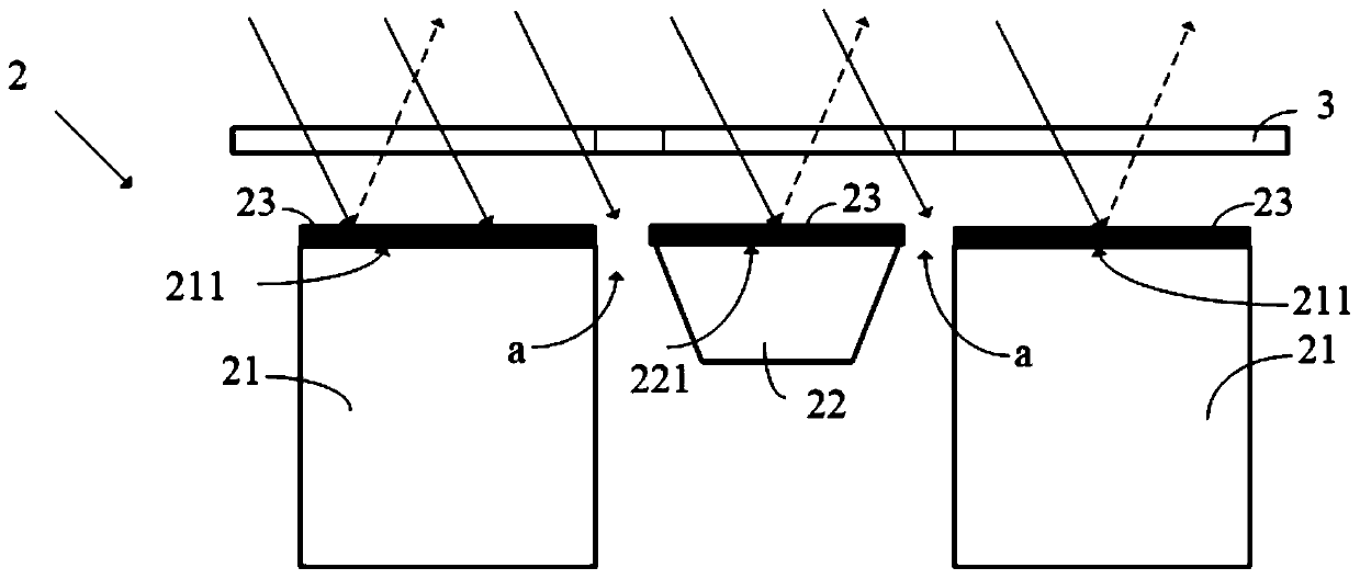
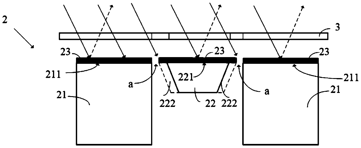
[0025] The technical solutions in the embodiments of the present application will be clearly and completely described below in conjunction with the drawings in the embodiments of the present application. Apparently, the described embodiments are only some of the embodiments of this application, not all of them. Based on the embodiments in this application, all other embodiments obtained by those skilled in the art without making creative efforts belong to the scope of protection of this application.

[0026] In the description of the present application, it should be understood that the terms "center", "longitudinal", "transverse", "length", "width", "thickness", "upper", "lower", "front", " Orientation indicated by rear, left, right, vertical, horizontal, top, bottom, inside, outside, clockwise, counterclockwise, etc. The positional relationship is based on the orientation or positional relationship shown in the drawings, which is only for the convenience of describing the a...


PUM

PropertyMeasurementUnit
thicknessaaaaaaaaaa
widthaaaaaaaaaa
reflectanceaaaaaaaaaa

Abstract

The invention discloses an exposure machine. The exposure machine comprises bearing tables used for bearing a substrate, a lifting rod spaced apart from the bearing tables, and a reflecting layer which is arranged on first sides of the bearing tables and arranged on a second side of the lifting rod, wherein the light reflectivity of the reflecting layer is smaller than that of the first sides andsmaller than that of the second side, the first sides are the sides, opposite to a mask plate, of the bearing tables, and the second side is the side, opposite to the mask plate, of the lifting rod. According to the invention, the reflecting layer with relatively low reflectivity is arranged on the first sides, opposite to the mask plate, of the bearing tables and the second side, opposite to themask plate, of the lifting rod, so that the light reflection difference of the bearing tables, the lifting rod and the gaps between the bearing tables and the lifting rod can be reduced, and the exposure uniformity of the substrate is improved.

Description

technical field [0001] The present application relates to the field of display technology, in particular to an exposure machine. Background technique [0002] During the manufacturing process of the display panel, it is necessary to use an exposure machine to expose the substrate multiple times. The exposure machine includes two carrying tables, and a lifting rod arranged between the two carrying tables. There is a gap area between the lifting rod and the adjacent bearing platform. [0003] When the exposure machine is used to expose the substrate panel through the mask plate, the light reflectance of the gap area is not only lower than that of the carrier table, but also lower than that of the lifting rod. This will result in uneven exposure to the substrate. [0004] Therefore, it is necessary to provide an exposure machine capable of uniformly exposing the substrate. Contents of the invention [0005] The embodiment of the present application provides an exposure ma...

Claims


Application Information

Patent Timeline
Patent Type & Authority Applications(China)
IPC IPC(8): G03F7/20
CPCG03F7/70716G03F7/70425
Inventor 袁继旺
Owner TCL CHINA STAR OPTOELECTRONICS TECH CO LTD
Why Eureka
Try Eureka