Electro-Optical Filter

a filter and optical technology, applied in the field of optical filters, can solve problems such as the challenge of imagining objects with a large dynamic brightness range, and achieve the effects of reducing light intensity differences, and large dynamic brightness

Inactive Publication Date: 2008-08-21
LIVE TECH
View PDF7 Cites 0 Cited by
  • Summary
  • Abstract
  • Description
  • Claims
  • Application Information

AI Technical Summary

Benefits of technology

[0005]a plurality of reflective elements for receiving and reflecting the light, each reflective element having an optical property that is dependent on an intensity of the light at or near the reflective element, the optical property controlling local filtering of the light intensity in a manner such that, above a predetermined intensity threshold, the filter reduces intensity differences of light originating from bright and dark regions of the object.
[0006]The electro-optical filter may be used for, or may be incorporated in, any type of image capturing or viewing instrument including for example a video camera, a still camera and a viewing instrument such as binoculars. As the filter reduces light intensity differences, objects having a large dynamic brightness can typically be imaged without loss of detail which is of significant practical advantage. Further, as the filter is a reflective device, control electronic and support material may be positioned behind a reflective surface of the filter and therefore do not impact on the light throughput in the same manner as in a transmissive device.

Problems solved by technology

Imaging of objects which have a large dynamic brightness range is a challenge.

Method used


Image

  • Electro-Optical Filter
  • Electro-Optical Filter
  • Electro-Optical Filter

Examples


Embodiment Construction

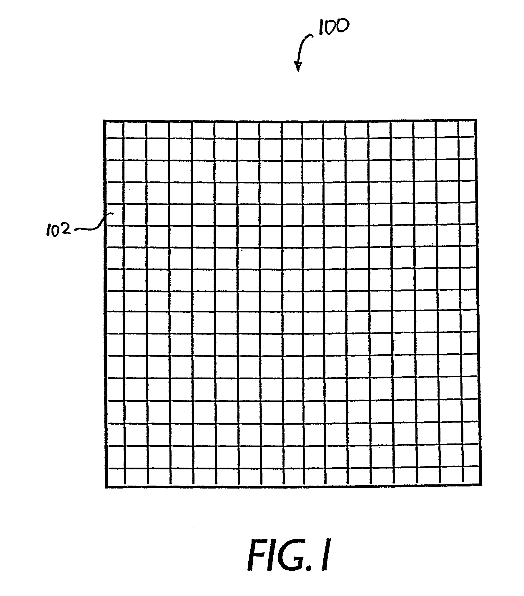
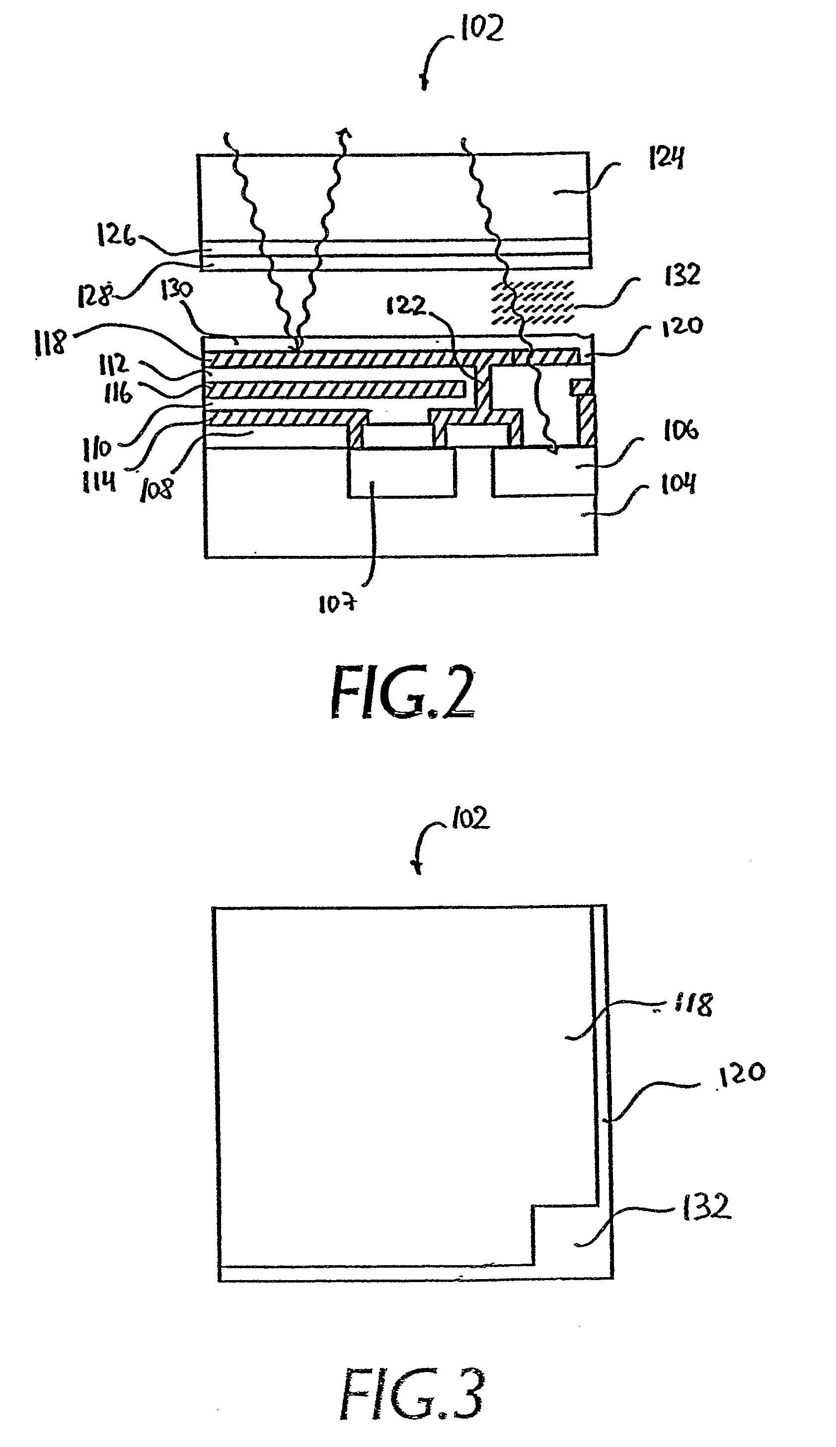
[0027]Referring initially to FIGS. 1 to 3, an electro-optical filter according to an embodiment of the present invention is now described. The electro-optical filter 100 comprises a matrix of reflective elements 102. In this embodiment the electro-optical filter 100 is fabricated using Liquid Crystal on Silicon (LCoS) technology which is often used for fabricating displays for projection devices and rear projection televisions.

[0028]Each reflective element 102 is in this embodiment formed on a silicon substrate 104 on which photodiode structures 106, 107 and transparent insulating layers 108, 110 and 112 are positioned. Further, the reflective element 102 comprises a plurality of metallic layers, such as layer 114 for drive circuitry wiring, layer 116 for drive circuitry wiring and voltage field shielding, and layer 118 which forms a reflective mirror-type electrode. Layer portion 120 defines a gap between adjacent reflective elements 102 in the matrix and a via 122 electrically con...


PUM

PropertyMeasurementUnit
angleaaaaaaaaaa
sizeaaaaaaaaaa
sizeaaaaaaaaaa

Abstract

The present invention provides an electro-optical filter for filtering light from an object. The filter is arranged for receiving the light via a first imaging element and comprises a plurality of reflective elements for receiving and reflecting the light. Each reflective element has an optical property that is dependent on an intensity of the light at or near the reflective element. The optical property controls local filtering of the light intensity in a manner such that, above a predetermined intensity threshold, the filter reduces intensity differences of light originating from bright and dark regions of the object.

Description

FIELD OF THE INVENTION [0001]The present invention broadly relates to an electro-optical filter.BACKGROUND OF THE INVENTION [0002]Imaging of objects which have a large dynamic brightness range is a challenge. For example, a camera may be adjusted for recording a bright image area within the camera's field of view, in which case a dark image area within the camera's field of view typically is underexposed on a recording medium. Alternatively, the camera may be adjusted for recording the dark image area in which case the bright image area is overexposed. In neither case is it possible to record all details at the bright and dark areas simultaneously.[0003]U.S. Pat. No. 5,953,082 describes a transmission filter that reduces intensity differences of light originating from bright and dark regions of the object and the present invention provides an alternative filter which has additional advantages.SUMMARY OF THE INVENTION [0004]The present invention provides in a first aspect an electro-...

Claims


Application Information

Patent Timeline
Patent Type & Authority Applications(United States)
IPC IPC(8): G02F1/13G02F1/1335
CPCG02F1/133553H04N5/238G02F1/135H04N23/75
Inventor BUTCHER, ROLANDSTEPHANOV, DMITRI YU
Owner LIVE TECH
Why Eureka
Try Eureka