Unlock instant, AI-driven research and patent intelligence for your innovation.

Crack fatigue detecting sensor, its mfg. and method for estimating failure using the same

A fatigue detection, crack type technology, applied in instruments, measuring devices, scientific instruments, etc., can solve problems such as management difficulties

Inactive Publication Date: 2005-03-30
KAWASAKI HEAVY IND LTD
View PDF1 Cites 1 Cited by
  • Summary
  • Abstract
  • Description
  • Claims
  • Application Information

AI Technical Summary

Problems solved by technology

This is sometimes not possible in practice and its management is very difficult

Method used


Image

  • Crack fatigue detecting sensor, its mfg. and method for estimating failure using the same
  • Crack fatigue detecting sensor, its mfg. and method for estimating failure using the same
  • Crack fatigue detecting sensor, its mfg. and method for estimating failure using the same

Examples


Embodiment Construction

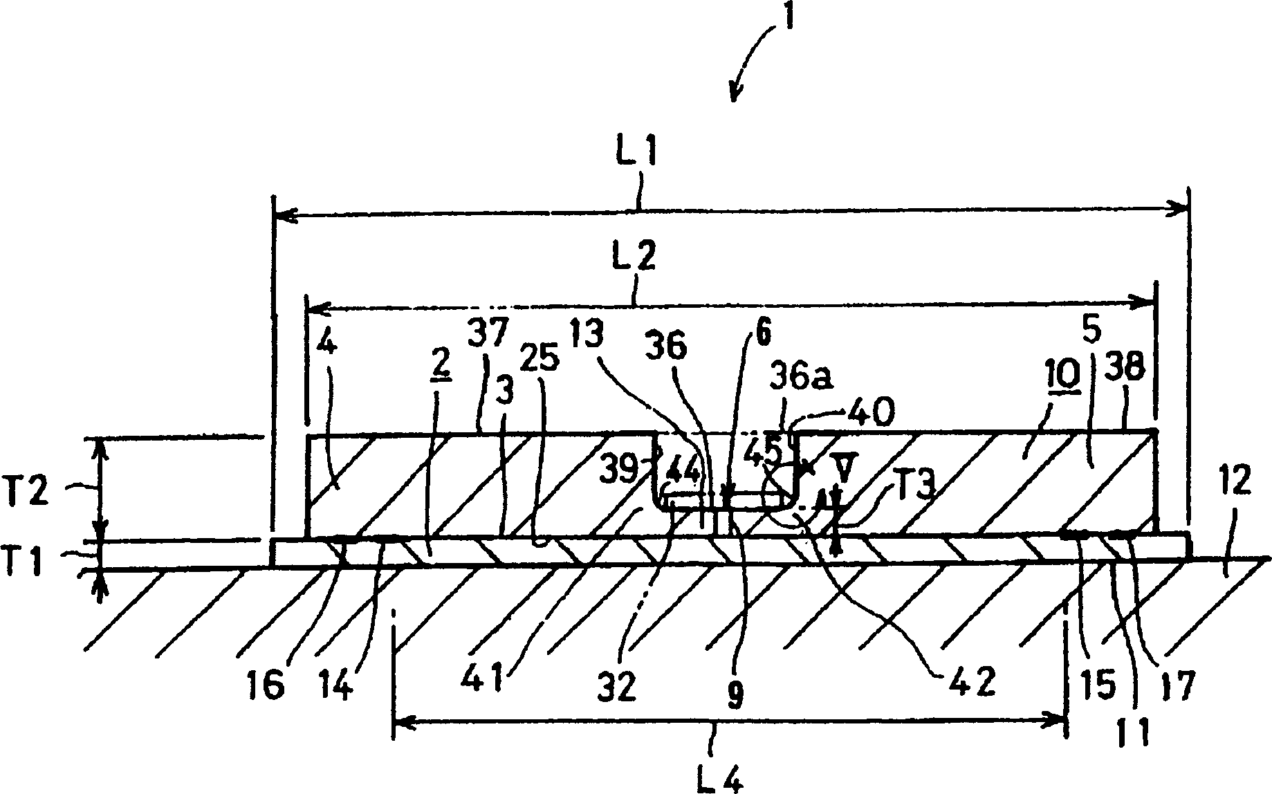
[0052] figure 1 Is a cross-sectional view of a crack type fatigue detection sensor according to an embodiment of the present invention, and figure 2 Yes figure 1 The floor plan of the crack type fatigue detection sensor. Hereinafter, a method for manufacturing the crack-type fatigue detection sensor 1 and a method of evaluating fatigue damage using the crack-type fatigue detection sensor 1 are also described. In order to reduce the long-term test cycle and cost, and to predict the service life of machines, components, etc. and extend their life, it is very important to accurately predict the life by non-destructively detecting the fatigue damage of the component to be tested. In order to measure life, that is, fatigue damage, the crack type fatigue detection sensor in this embodiment (hereinafter referred to as fatigue detection sensor) is used.

[0053] Now refer to figure 1 , 2 , Shows the fatigue detection sensor 1. In the fatigue detection sensor 1, the broken metal sheet...


PUM


Abstract

A crack-type fatigue detecting sensor comprises: a foil substrate having a first surface and a second surface fixed to a member to be tested; and a foil fracture piece having a slit formed in a central portion between opposite end portions in a longitudinal direction thereof such that the slit extends from one side portion toward the other side portion in a width direction thereof perpendicular to the longitudinal direction, wherein the opposite end portions of the fracture piece are respectively fixed to the first surface of the substrate and a portion including the central portion having the slit has a thickness smaller than a thickness of the opposite end portions over a whole width.

Description

Technical field [0001] The present invention relates to a crack type fatigue detection sensor, a method for manufacturing a crack type fatigue detection sensor, and a method for evaluating damage by using the crack type fatigue detection sensor, which is suitable for practical use in measuring damage such as bridges, machines, automobiles, and airplanes. Damage caused by fatigue of different components of such structural components. Background technique [0002] A general prior art is disclosed in Japanese Patent No. Sho. 62-265558 that has been published. The prior art discloses a crack type fatigue detection sensor, in which a broken sheet with a notch that causes fatigue is fixed on the surface of a flat-plate-shaped substrate; a method for manufacturing a crack type fatigue detection sensor, wherein The opposite end portions (in the length direction) of the cut broken sheet are pasted on the surface of the substrate by an adhesive for fixing; and a method for evaluating damag...

Claims


Application Information

Patent Timeline
IPC IPC(8): G01M99/00G01B5/30G01M5/00G01N3/00G01N3/06G01N3/32G01N27/20
CPCG01N3/06G01M5/0083G01B5/30G01N2203/0062G01N27/205G01M5/0033G01M7/00
Inventor 仁瓶宽太小林朋平尾野英夫公江茂树村上彰男西山五郎嵩良德
Owner KAWASAKI HEAVY IND LTD