
Disc device

一种光盘装置、光盘的技术,应用在光束源、光学记录头、光学记录系统等方向,能够解决起伏或误差率不良、影响、反复记录耐久性不良等问题

Inactive Publication Date: 2006-10-04
TEAC CORP
View PDF0 Cites 0 Cited by
  • Summary
  • Abstract
  • Description
  • Claims
  • Application Information

AI Technical Summary

Problems solved by technology

And when it is difficult to determine the original optimal recording power, it will be difficult to maintain the recording quality (waveform fluctuation, error rate, etc.)
Specifically, when using recording power significantly lower than the original optimum recording power for recording, it will cause adverse effects on fluctuation or error rate; conversely, when using significantly higher than the original optimum recording power In the case of recording with recording power, it will have a bad influence on the durability of repeated recording.

Method used


Image

  • Disc device
  • Disc device
  • Disc device

Examples


Embodiment Construction

[0043] Next, preferred embodiments of the present invention will be described with reference to the drawings.

[0044] first preferred embodiment

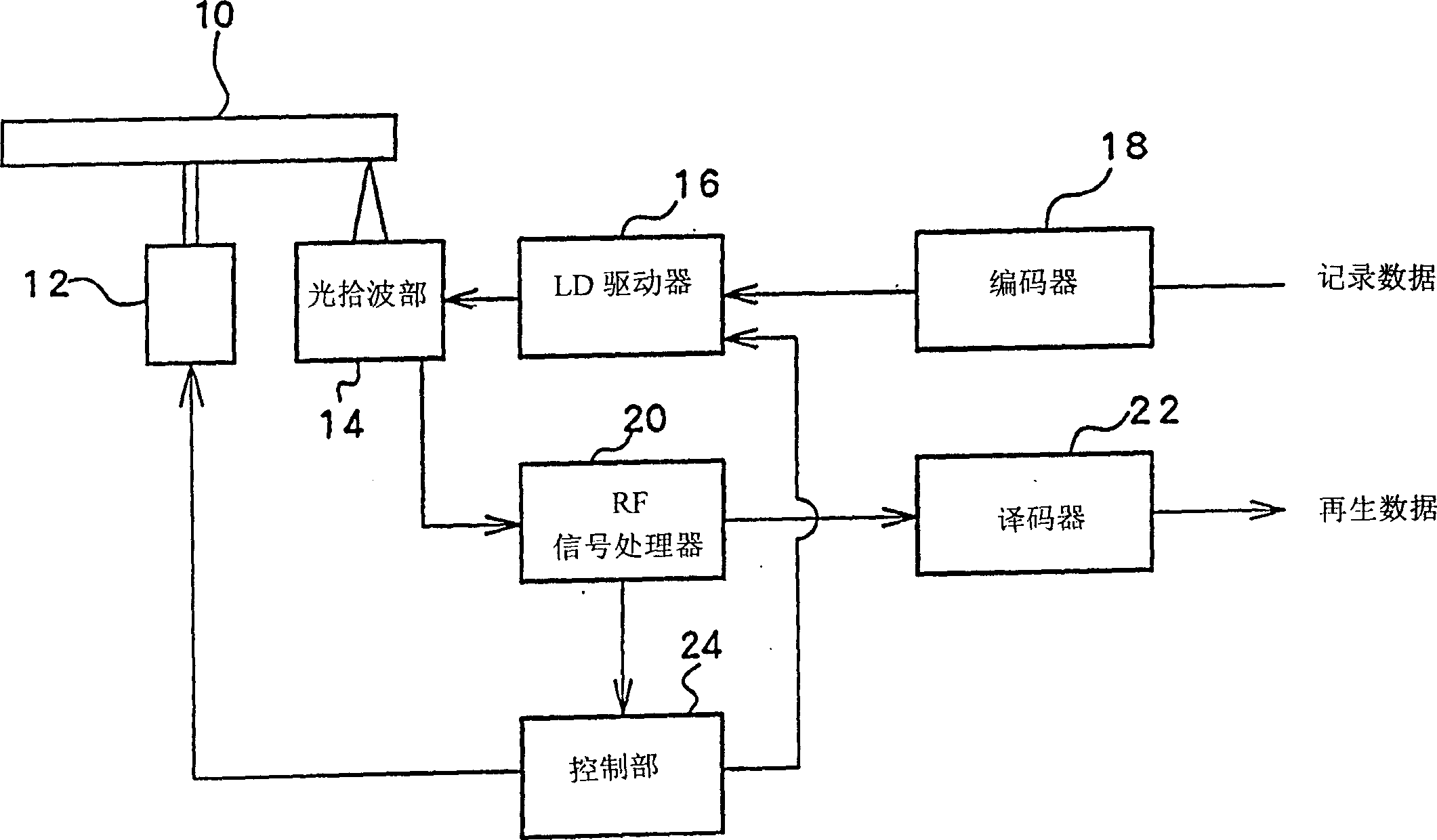
[0045] figure 1 Shown is a block diagram of a partial structure of the optical disc device in this preferred embodiment.

[0046]The optical disc 10 is CLV-controlled or CAV-controlled by a spindle motor 12 . On the opposite side of the optical disc 10, an optical pick-up (light pick-up) part 14 is arranged, and the laser light of the recording power is emitted from a laser diode (laser diode, LD), and data is recorded on the optical disc 10, and moreover, the laser light emitted from the LD is reproduced. A high-power laser can read the recorded data. In addition, when the optical disc 10 is a rewritable optical disc, laser light with erasing power (reproducing power


PUM


Abstract

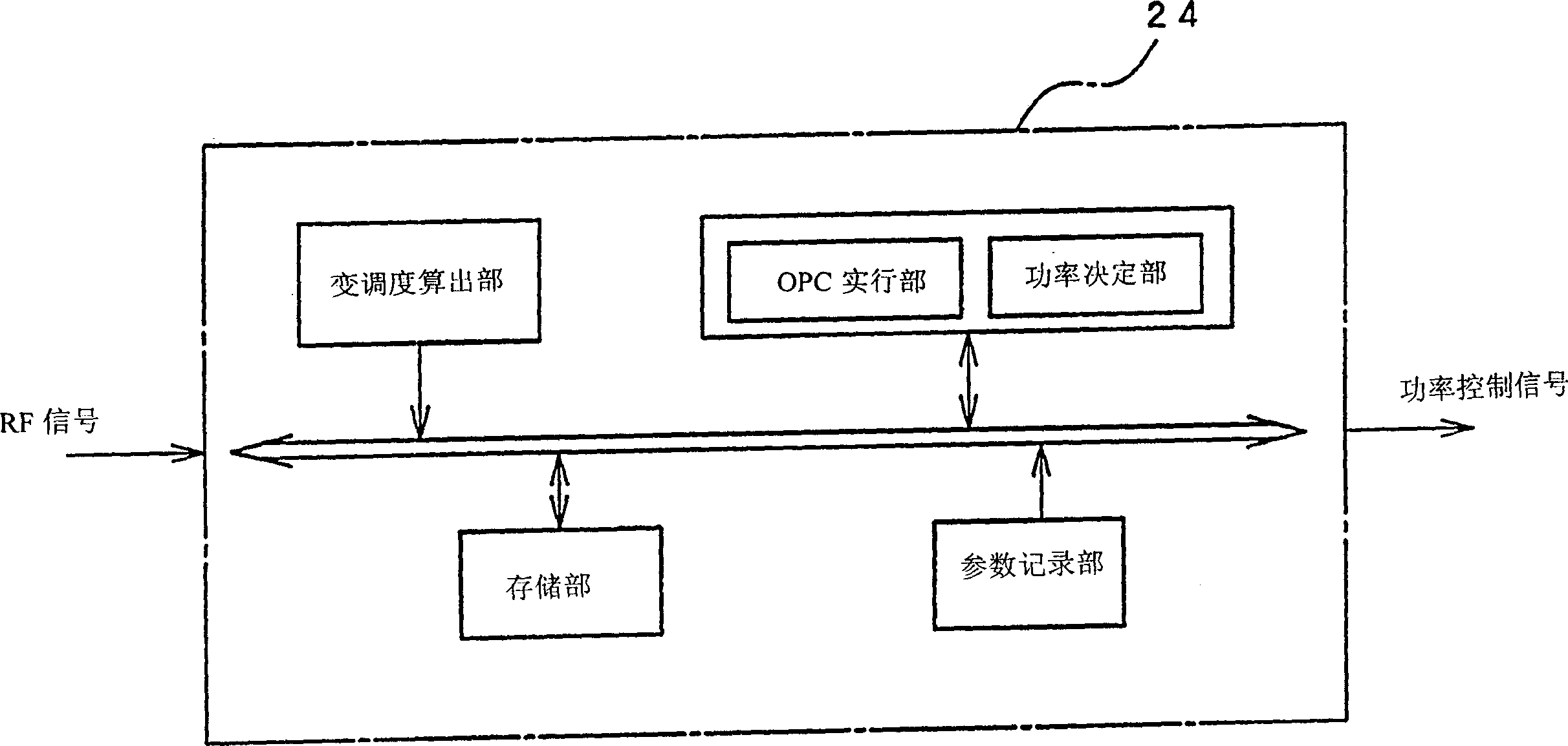
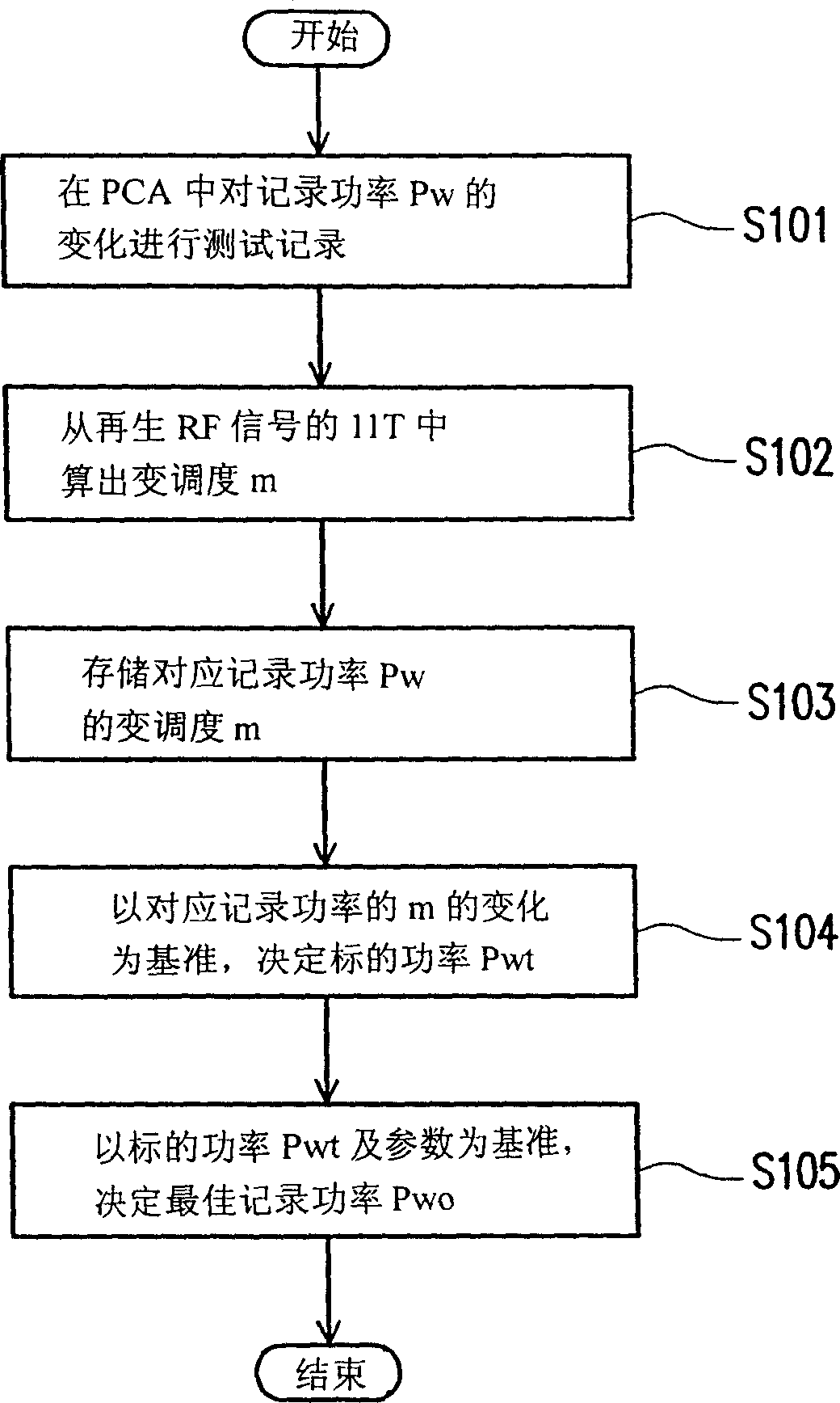
An optical disk apparatus can optimize recording power in a recording-capable optical disk. The recording power is optimized by an OPC. A controlling part diversifies the recording power to record test data and computes the modulation factor m of a reproducing RF signal. An inflection point where the inclination of variation of the modulation factor m to the recording power varies is extracted, and the optimum recording power is a value obtained by the multiplication by a prescribed parameter to the recording power corresponding to the inflection point as the target recording power. The target recording power is a recording power whose modulation factor m becomes zero from the inclination in variation to the recording power of the modulation factor m, and the optimum recording power is obtained by the multiplication by the prescribed parameter to the target recording power.

Description

technical field [0001] The present invention relates to an optical disc device, and more particularly to a technique for optimizing recording power when recording data on a recordable optical disc. Background technique [0002] In the public knowledge, the specified field of the optical disc is specifically in the power calibration area (Power Calibration Area, PCA) formed in the inner peripheral part of the optical disc, under the recording power divided into multiple segments, test and record the random EFM data of the change, and A well-known OPC technique for optimizing recording power. Specifically, from the reproduced RF signal of the test recording data, it can be calculated by the power function (γ). Recording power is used as a reference to determine the optimum recording power. Furthermore, the γ value is defined as follows based on the modulation degree m of the reproduced RF signal and the recording power Pw. [0003] [mathematical formula 1] [0004] γ=(dm / d...

Claims


Application Information

Patent Timeline
Patent Type & Authority Patents(China)
IPC IPC(8): G11B7/00G11B7/0045G11B7/125G11B7/126
CPCG11B7/126G11B7/1263G11B7/0045
Inventor 福地洁久保充正
Owner TEAC CORP
Learn More