CD recorder and CD record medium

A disc recording and optical disc technology, which is applied in optical recording heads, optical recording systems, optical recording/reproduction, etc., can solve the problem of less parameters, deterioration of optical disc durability, and larger sum of recording power and erasing power And other issues

Inactive Publication Date: 2006-03-15
TEAC CORP
View PDF0 Cites 0 Cited by
  • Summary
  • Abstract
  • Description
  • Claims
  • Application Information

AI Technical Summary

Problems solved by technology

[0016] As known, OPC is used to determine the optimum recording power P wo , and multiply the best recording power by the corresponding fixed value coefficient ε to obtain the best erasing power P eo , and the method of setting the recording cooling power to a fixed power is a method with few parameters and easy setting. However, under the cooperation of the optical disc and the optical pickup, the recording power is affected by dispersion. When , the erasing power also becomes larger, so that the sum of recording power and erasing power also becomes larger, thus causing the problem of deterioration of the durability of the optical disc for repeated recording
On the contrary, the recording power is affected by dispersion. When the recording power becomes smaller, the erasing power also becomes smaller, which causes the problem of deterioration of the erasing characteristics.

Method used


Image

  • CD recorder and CD record medium
  • CD recorder and CD record medium
  • CD recorder and CD record medium

Examples


Embodiment Construction

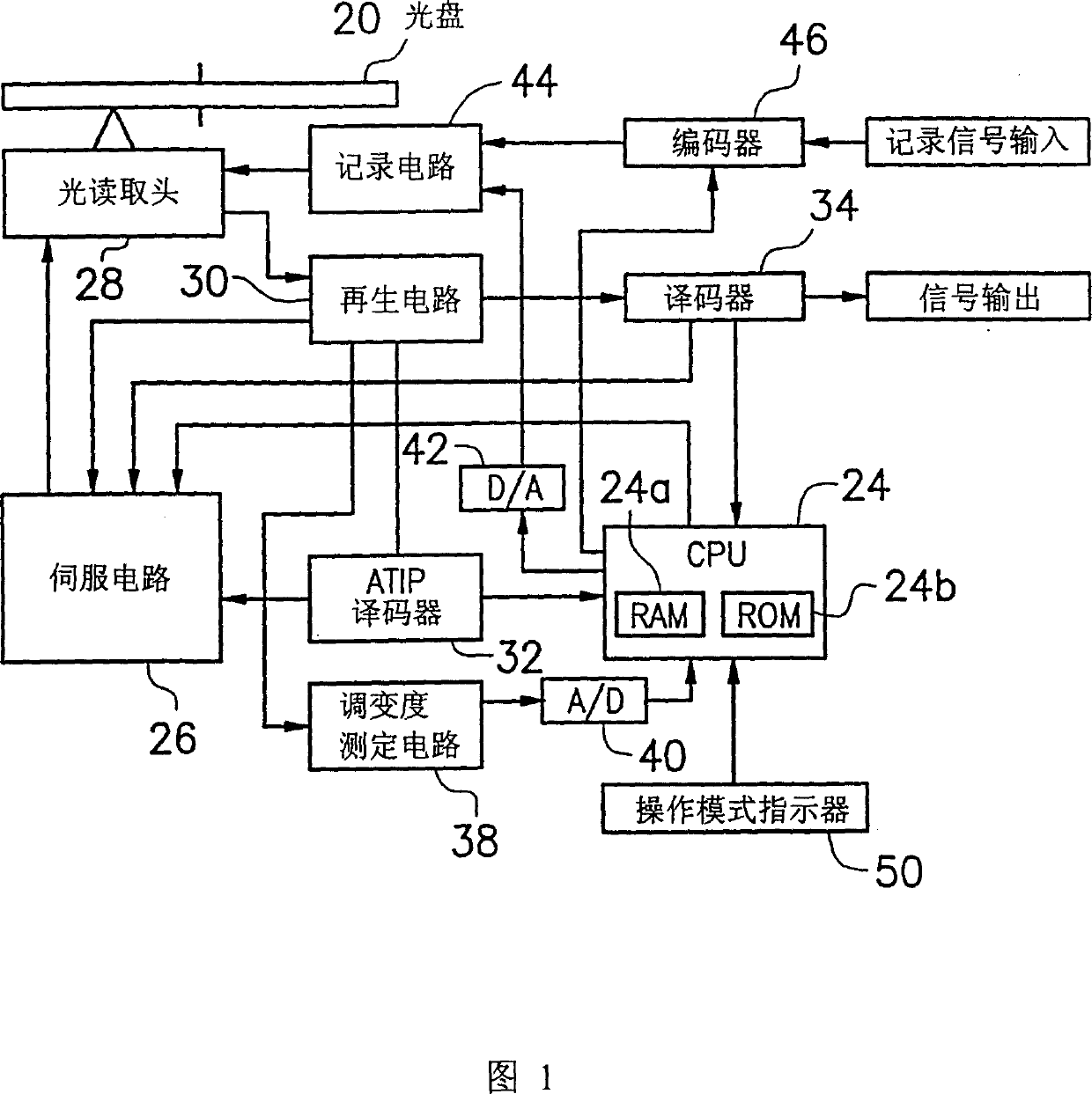
[0041] FIG. 1 is a schematic block diagram of an embodiment of an optical disc recording device of the present invention. As shown in the figure, the optical disc 20 rotates around a shaft 22 driven by a spindle motor. The CPU 24 provides commands to the servo circuit 26 according to the write / read commands provided by the host device.

[0042] The servo circuit 26 is to carry out the above-mentioned constant linear velocity (constant linear velocity, CLV) servo control of the spindle motor, and carry out the rotation control of the sled motor (sled motor) of the optical pick-up head 28, so that the optical pick-up head 28 moves to the optical disc. 20, and perform focus servo and tracking servo control of the optical pickup head 28.

[0043] The laser beam irradiated by the optical pick-up head 28 will be reflected by the recording surface of the optical disc 20, and the reflected light will be detected by the optical pick-up head. The reproduced RF signal obtained at the o...


PUM


Abstract

An optical recording apparatus comprises an optimum recording power calculating device, capable of varying a recording power to perform a recording process on a test recording area of the erasable optical disc, and calculating an optimum recording power according to signals that reproduce the test recording area; and an optimum erasing power calculating device, for calculating an optimum erasing power from the optimum recording power and a coefficient corresponding to the optimum recording power. The optimum recording power and the optimum erasing power are used for recording the erasable optical disc. Thereby, even though the dispersion of the recording power becomes large, the erasing power is not greater than a certain range; therefore, the total of the recording power and the erasing power can be restrained and the degradation of the durability, that the optical disc can be repeatedly recorded, can be suppressed.

Description

technical field [0001] The present invention relates to an optical disc recording device and an optical disc recording medium, and in particular relates to an optical disc recording device and an optical disc recording medium for recording erasable optical discs. Background technique [0002] Recording optical discs can be classified into write once type such as CD-R and erasable type such as CD-RW. Among them, as shown in FIG. 5, when recording overwrite (over write) for an erasable optical disc, the laser beam laser power used is at the recording power P w , record cooling power P c and the erase power P e Vary among the three values. In this case, the recording power P w The power to raise the temperature of the recording layer (phase change layer) to the melting point. Record cooling power P c It is low power for extremely cooling the recording layer (phase change layer) from the melting point to the amorphous state. Erase power P e It is the power to raise the t...

Claims


Application Information

Patent Timeline
Patent Type & Authority Patents(China)
IPC IPC(8): G11B7/004G11B7/0045G11B7/0055G11B7/006G11B7/125G11B7/126
CPCG11B7/006G11B7/00557G11B7/00454G11B7/126G11B7/1263G11B7/0045
Inventor 真下著明石森靖英
Owner TEAC CORP
Why Eureka
Try Eureka