
Optical disc apparatus and information recording method

An optical disc device and optical disc technology, applied in the direction of optical recording/reproducing/erasing methods, optical recording heads, optical recording systems, etc., can solve the problems of reproduction quality degradation, deviation, and optimal recording pulse edge position deviation, etc., to achieve The effect of improving usability

Inactive Publication Date: 2009-03-04
HITACHI CONSUMER ELECTRONICS CORP +1
View PDF6 Cites 0 Cited by
  • Summary
  • Abstract
  • Description
  • Claims
  • Application Information

AI Technical Summary

Problems solved by technology

[0002] Generally speaking, in an optical disc device, OPC (Optimum Power Control: Optimum Power Control) processing is performed prior to the recording operation, so that a recording pulse with an optimal recording power in a prescribed recording strategy can be generated, but the optical disc device itself Deviations in performance and deviations of the optical disc, etc., often cause the best recording pulse edge position of the recording pulse to deviate
If the pulse edge position of the recording pulse is not appropriate, the mark length and edge position of the recording mark recorded on the optical disc will deviate from the appropriate range, and the reproduction quality of information such as image jitter characteristics will deteriorate during reproduction.

Method used


Image

  • Optical disc apparatus and information recording method
  • Optical disc apparatus and information recording method
  • Optical disc apparatus and information recording method

Examples


Embodiment Construction

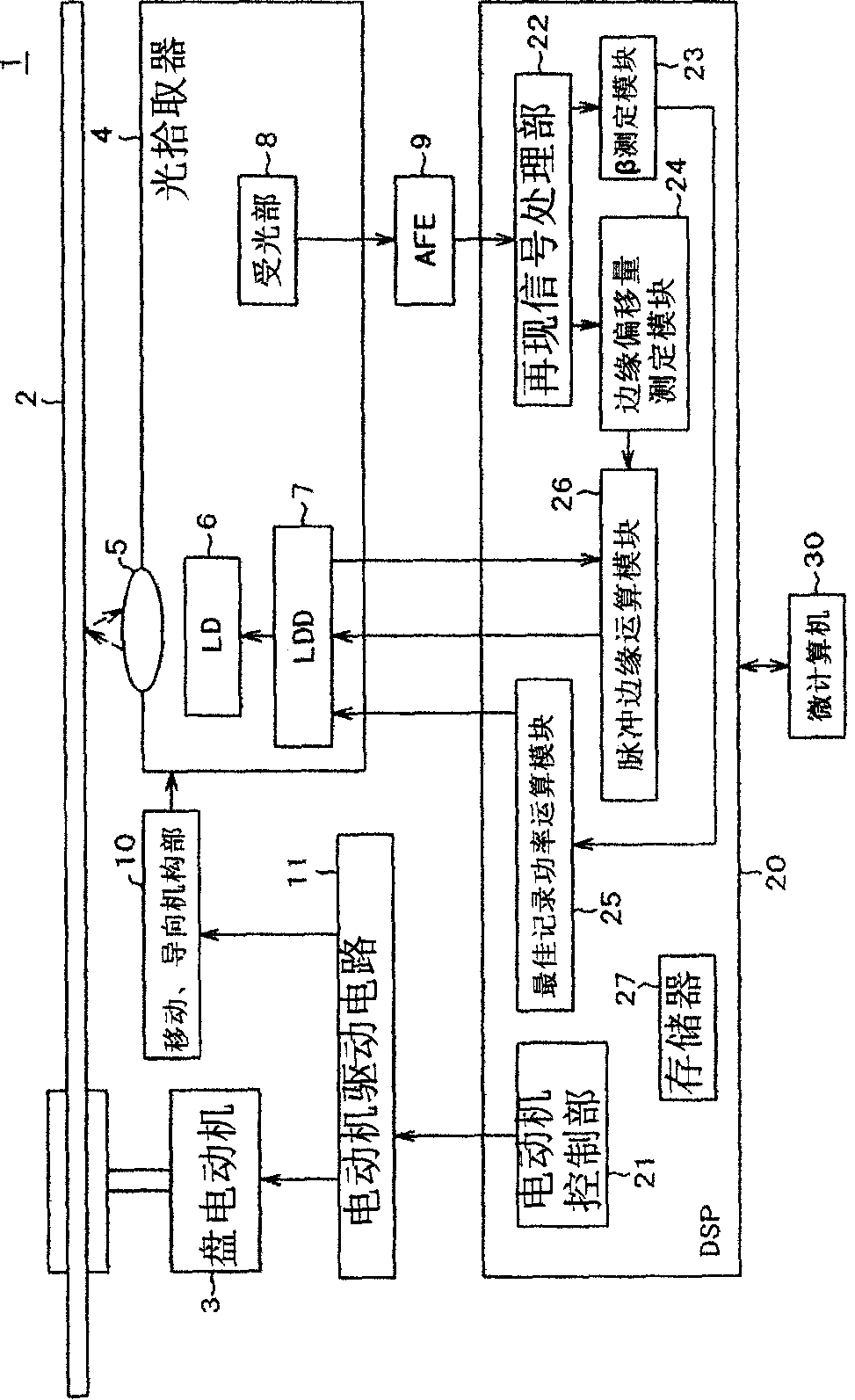
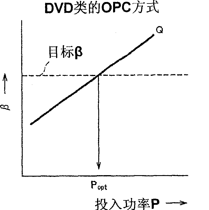
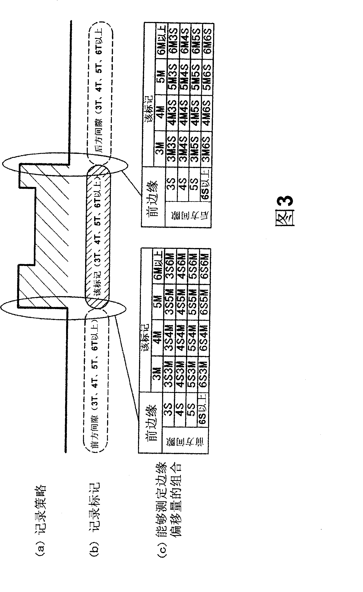
[0014] Hereinafter, embodiments of the present invention will be described with reference to the drawings. Figure 1 to Figure 6 It is explanatory drawing of embodiment of this invention. figure 1 is a configuration example diagram of an optical disc device as an embodiment of the present invention, figure 2 yes figure 1 Figure 3 is an explanatory diagram of OPC (Optimum Power Control: Optimum Power Control) processing in the optical disc device of figure 1 An explanatory diagram of a combination capable of measuring the edge shift amount of a recording mark in an optical disc device, FIG. 4 is figure 1 An explanatory diagram of the edge shift of the recording mark in the optical disc device, Figure 5 is in figure 1 An explanatory diagram of the method of obtaining the optimum pulse edge position of the recording pulse based on the measurement result of the edge shift amount in the optical disc device of , Image 6 yes figure 1 An explanatory diagram of the operation o...


PUM


Abstract

Provided is a technology for improving the recording quality through edge correction of recording pulse in an optical disc apparatus. An optimum recording power of recording pulse is obtained through OPC processing according to a recording strategy with a first pulse timing; recording is performed by use of recording pulse with the optimum recording power; a first edge-shift amount of recording mark is measured from a reproduction signal to perform edge correction of recording pulse to form a second pulse timing of a recording strategy. Subsequently, recording is performed with pulse width variations of recording pulse to measure a second edge-shift amount of recording mark from a reproduction signal; and optimum edge positions of recording pulse are calculated based on the first edge-shift amount and the second edge-shift amount.

Description

technical field [0001] The present invention relates to an information recording technique in an optical disc device, and particularly relates to a technique for correcting the edge of a recording pulse in a predetermined recording strategy. Background technique [0002] Generally speaking, in an optical disc device, OPC (Optimum Power Control: Optimum Power Control) processing is performed before the recording operation, so that a recording pulse with an optimal recording power in a prescribed recording strategy can be generated, but the optical disc device itself The optimum recording pulse edge position of the recording pulse often deviates due to variations in performance, variations in the optical disc, and the like. If the pulse edge position of the recording pulse is inappropriate, the mark length and edge position of the recording mark recorded on the optical disc deviate from the appropriate range, deteriorating the reproduction quality of information such as image ...

Claims


Application Information

Patent Timeline
Patent Type & Authority Patents(China)
IPC IPC(8): G11B7/0045G11B7/125
CPCG11B7/1267G11B7/00456
Inventor 石井利树户田刚伏见哲也今井雅士
Owner HITACHI CONSUMER ELECTRONICS CORP
Learn More