Clean container structure

A technology for cleaning containers and fixing structures, which is applied in the manufacture of semiconductor/solid-state devices, packaging of vulnerable items, electrical components, etc. It can solve the problems of many dead ends, high cost, difficult manufacturing and assembly, etc., and achieve excellent force transmission methods. , the production cost is reduced, the effect of improving the retention effect

Inactive Publication Date: 2007-05-02
IND TECH RES INST
View PDF5 Cites 1 Cited by
  • Summary
  • Abstract
  • Description
  • Claims
  • Application Information

AI Technical Summary

Problems solved by technology

[0004] However, the design in which an upper assembly hole 913 and a lower assembly hole 914 are directly provided on the upper side plate 911 and the lower side plate 912 of the clean container body 91 is not only difficult and expensive to manufacture and assemble, but also It is also easy to cause the structural strength of the clean container body 91 to be damaged
In addition, the clean container body 91 has too many openings and the area is too large, and the airtightness of the inner chamber 910 is also easily affected, so it is easy to cause external moisture or dust particles to enter, which is not very ideal, and can only be added. Airtight gasket to strengthen its airtight effect
In addition, since there are too many dead angles in components such as the clean container body 91, it is easy to cause the phenomenon that cleaning and drying are not easy when using related cleaning equipment for cleaning.

Method used


Image

  • Clean container structure
  • Clean container structure
  • Clean container structure

Examples


Embodiment Construction

[0032] In order to further understand the technical content of the present invention, two preferred specific embodiments are illustrated as follows.

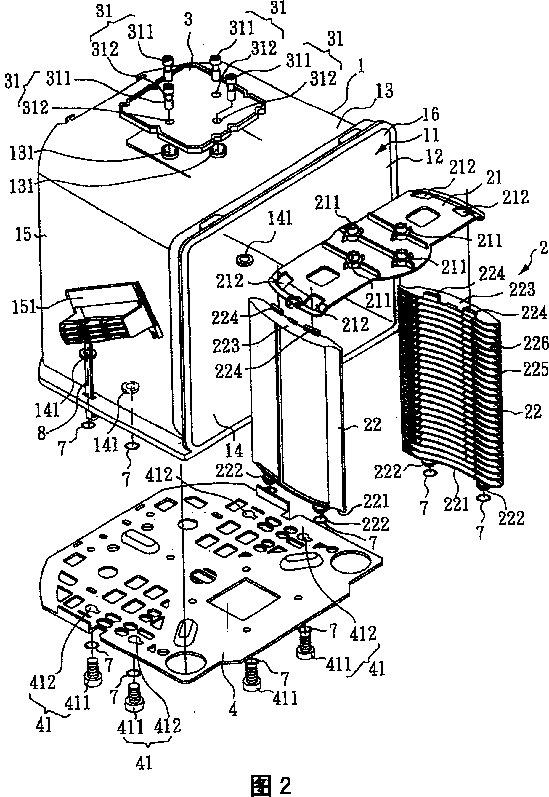
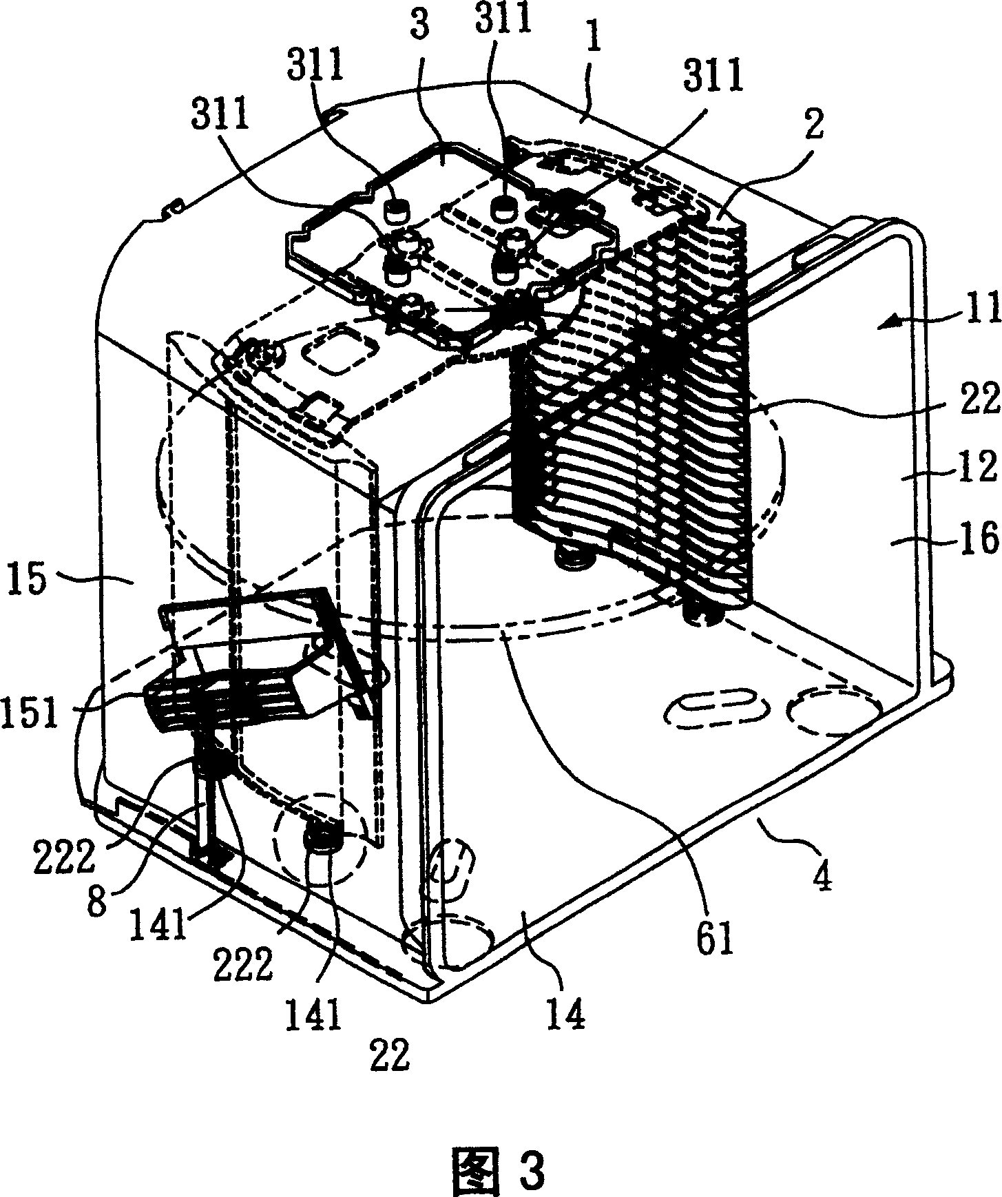
[0033] Please also refer to FIG. 2 which is an exploded perspective view of the first preferred embodiment of the present invention, FIG. 3 is a perspective combined view of the first preferred embodiment of the present invention, and FIG. 4 is a sectional view of the fixing structure and fixing components of FIG. 3 , which shows a clean container structure, which includes a clean container body 1, a support frame 2, an upper take-off plate 3, and a lower take-off plate 4.

[0034] The clean container body 1 among the accompanying drawings also includes an inner chamber 11, a front opening 12, an upper plate 13, a lower plate 14, a left side plate 15, and a right side plate 16, on the left side plate The outer group of 15 is provided with a left handle 151, is provided with a right handle (not shown) in the opposite group on the...


PUM


Abstract

A clean container is disclosed. A bracing frame is placed into the clean container directly from it's front opening, which is made integrally with the inner chamber of the clean container. There is an upper assistant plant at the upper part of the container and there is a lower assistant plate at the lower part of the container. The two plates are combined with the bracing frame. Advantages: simple production and assembling, good structure strength and air tightness.

Description

technical field [0001] The invention relates to a clean container structure, in particular to a clean container structure which is suitable for rationalizing the transmission mode of load-carrying force, and can improve structural strength and precision, air tightness, and electrostatic protection. Background technique [0002] At present, the wafers produced by the semiconductor factory are often accommodated and arranged horizontally in a wafer boat. The wafer boat has a plurality of supporting flanges and can be used to insert multiple wafers. The lower side plate of the clean container body is then covered by the cover of the clean container body to protect each wafer, so that it can maintain ultra-high cleanliness during the process of transmission, storage, loading and unloading during production and manufacturing environment without being polluted by particulate dust. [0003] Please refer to Fig. 1, which is a three-dimensional exploded view of a known clean contain...

Claims


Application Information

Patent Timeline
Patent Type & Authority Patents(China)
IPC IPC(8): B65D85/86B65D85/30H01L21/00
Inventor 吴宗明何天露
Owner IND TECH RES INST
Why Eureka
Try Eureka