Supercharge Your Innovation With Domain-Expert AI Agents!

Guide bar

A technology of guide rods and protruding parts, applied in the field of guide rods, can solve the problems of increasing friction, increasing wear of guide rod saw chains, increasing lateral movement, etc.

Inactive Publication Date: 2007-07-25
HUSQVARNA AB
View PDF7 Cites 0 Cited by
  • Summary
  • Abstract
  • Description
  • Claims
  • Application Information

AI Technical Summary

Problems solved by technology

Increased lateral movement and increased friction also increases wear on the guide bar and saw chain

Method used


Image

  • Guide bar
  • Guide bar

Examples


Embodiment Construction

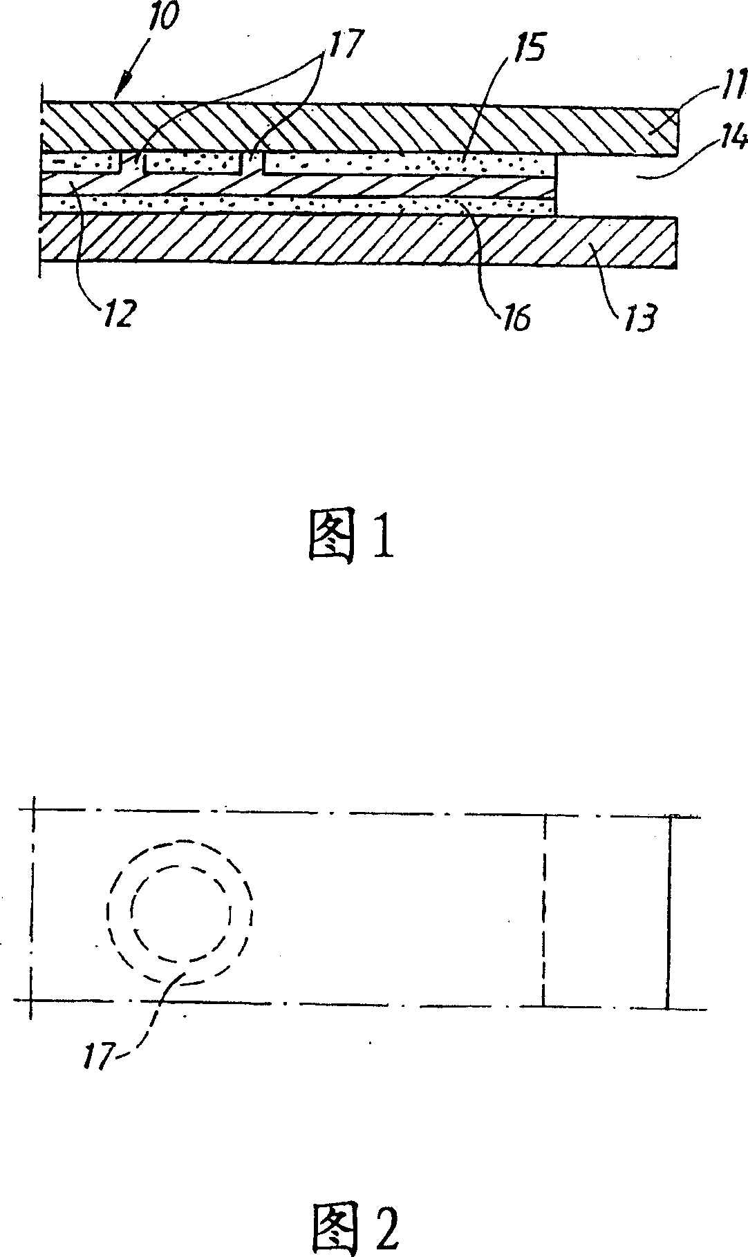
[0025] The guide rod 10 comprises three layers 11 , 12 , 13 . The first layer 11 and the third layer 13 are identical in shape, while the middle layer 12 is shorter and slightly smaller in width. When these three layers 11 , 12 , 13 are put together, a groove 14 is defined around the guide rod 10 due to the smaller size of the middle layer 12 . Slot 14 is used for a saw chain, not shown.

[0026] The guide rod 10 comprises three different layers 11 , 12 , 13 bonded together by two layers of adhesive material 15 , 16 acting on almost the entire surface in contact with each other.

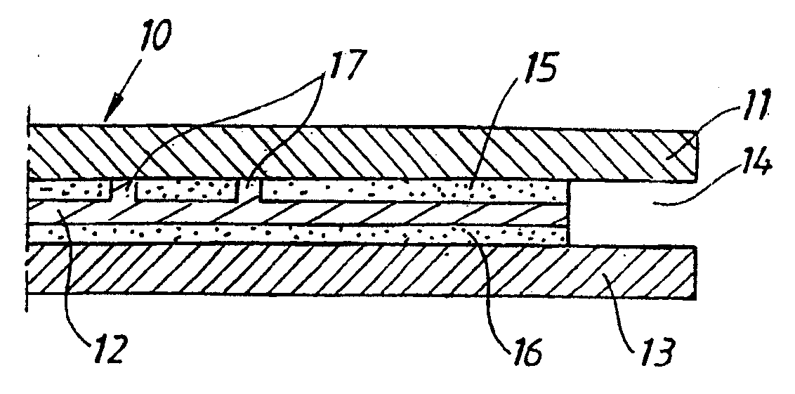
[0027] The intermediate layer 12 is provided with a plurality of protrusions 17 . When the layers are brought together, the protrusion 17 creates a slot between the layers. The protrusion 17 controls the width of the slot and thus the thickness of the adhesive layer so that the maximum strength of the two bonds is achieved. The constant and precise width of this slot is important to ensure that t...


PUM


Abstract

The claimed invention relates to a device in a guide bar (10) for a chain saw. The guide bar (10) comprises at least two layers (11, 12, 13) that are bounded by an adhesive material. To ensure that the layer of adhesive material gets the optimal thickness is one of the surfaces of the layers that will be bounded to each other provided with several protruding parts (17). The protruding parts (17) will generate a slot, with the same width as the height of the protruding parts, for the adhesive material when the layers are put together. This is important to ensure maximum strength in the bounding as well as a constant width of a groove (14) for the saw chain.

Description

technical field [0001] The present invention relates to guide bars used in chainsaws. Such guide rods comprise at least two layers bonded together by an adhesive material. Background technique [0002] Chainsaws and other hand tools have been highly developed over the past few years. Significant efforts have been made to improve the performance and ergonomics of these tools. [0003] New materials and methods of manufacturing the different components have made it possible to reduce the weight of these tools. These tools are also stronger and more reliable, thus greatly improving the working conditions for the operator. Great achievements have been made in terms of mechanics and housings, however, the development of guide rods also encountered serious problems. The biggest problem is that all new solutions to reduce the weight of the guide rods are terminated due to the degradation of the guide rod performance due to the reduced torsional stiffness and / or bending stiffnes...

Claims


Application Information

Patent Timeline
Patent Type & Authority Patents(China)
IPC IPC(8): B27B17/02
CPCY10T83/909B27B17/025
Inventor 罗杰·赫尔曼松约翰·弗拉滕伦纳特·艾克鲁德特耶·伯格特
Owner HUSQVARNA AB
Features
  • R&D
  • Intellectual Property
  • Life Sciences
  • Materials
  • Tech Scout
  • Unparalleled Data Quality
  • Higher Quality Content
  • 60% Fewer Hallucinations
Learn More