Detection of rotating direction

A technology of rotation direction and rotation axis, applied in the directions of indicating/recording actions, devices using electric/magnetic methods, measuring devices, etc., which can solve the problems of complicated and expensive devices, easy to damage, difficult to manufacture and install, etc.

Inactive Publication Date: 2002-02-06
INFINEON TECH AG
View PDF0 Cites 18 Cited by
  • Summary
  • Abstract
  • Description
  • Claims
  • Application Information

AI Technical Summary

Problems solved by technology

However, such devices are usually complex and expensive, and require sensitive electronic and mechanical devices that are easily damaged and difficult to manufacture and install
In addition, such devices usually require a constant power supply connection, which is often a high power consumption class device

Method used


Image

  • Detection of rotating direction
  • Detection of rotating direction
  • Detection of rotating direction

Examples


Embodiment Construction

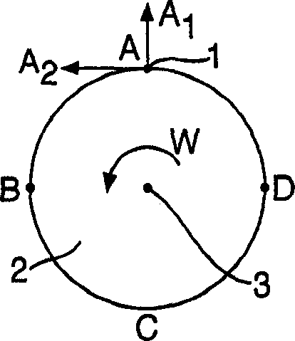
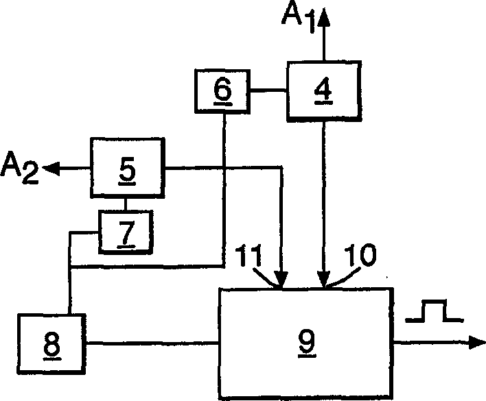
[0020] see figure 1 , the device 1 of the present invention is positioned on the periphery of a rotating object 2 whose direction of rotation is to be determined. Object 2 can rotate around axis 3 in either direction. The following combination image 3 Describing the device 1 of the invention in more detail, image 3 It includes two accelerometers 4, 5 each with a senseable direction A1, A2, and the change of acceleration force on the accelerometers 4, 5 can be measured through the corresponding accelerometers 4, 5 in the directions A1, A2.

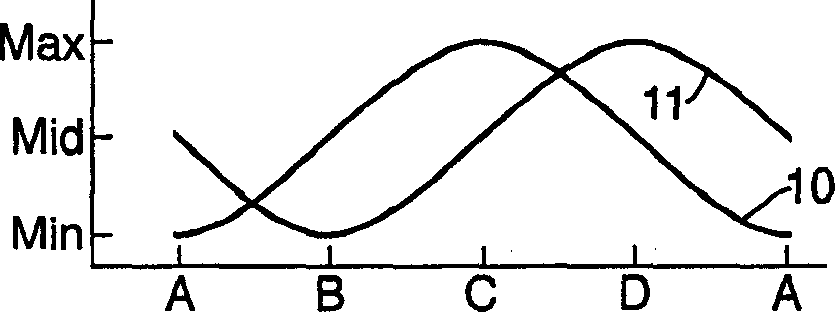
[0021] In this example, the accelerometers 4, 5 are fixed at the same location on the periphery of the object 2, although this is not required. In addition, in this example, the detection directions A1 and A2 are perpendicular to each other, but this is not necessary. In order for the device to work, the accelerometers 4,5 must be positioned on the object and their detection directions arranged so that the phase difference between the...


PUM


Abstract

A sensor for sensing a direction of rotation of a body. The sensor comprises a first accelerometer arranged, in use, on the body, and having a first sensing direction; and a second accelerometer arranged, in use, on the body and having a second sensing direction. The two accelerometers are arranged such that the first and second sensing directions are not parallel to one another and are not parallel to the axis of rotation of the body, such that there is a phase difference due to gravitational effects between the outputs of the accelerometers when the body rotates in use. Means receives the acceleration indicative output signals from the first and second accelerometers and determines the phase relationship between the two signals to thereby determine the direction of rotation of the body.

Description

technical field [0001] The invention relates to a device for detecting the direction of rotation of a rotating object such as a wheel. Background technique [0002] A number of devices have been proposed for providing a signal indicating the direction of rotation of a rotating body and for providing an indication of the rotational speed of the rotating body. However, such devices are generally complex and expensive, and require sensitive electronic and mechanical devices that are easily damaged and difficult to manufacture and install. In addition, such devices usually require a constant power supply connection, which is often a power-hungry class of devices. Contents of the invention [0003] Therefore, there is a need for an inexpensive, low power consumption device that is reliable and simple in construction and provides an output indicating the direction of rotation of a rotating object. [0004] According to the present invention, a sensor for detecting the directio...

Claims


Application Information

Patent Timeline
Patent Type & Authority Applications(China)
IPC IPC(8): G01P3/44G01P13/04G01P15/00
CPCG01P3/44G01P13/045G01P13/04
Inventor R·霍尔姆
Owner INFINEON TECH AG
Why Eureka
Try Eureka