Casing structure for fixing and containing shank

A shell structure and shell technology, applied in medical science, fractures, etc., can solve the problems of unintentional, wrong adjustment, etc., and achieve the effect of easy production

Inactive Publication Date: 2011-04-27
OPED
View PDF0 Cites 0 Cited by
  • Summary
  • Abstract
  • Description
  • Claims
  • Application Information

AI Technical Summary

Problems solved by technology

On the other hand, it can also lead to unintentional wrong

Method used


Image

  • Casing structure for fixing and containing shank
  • Casing structure for fixing and containing shank
  • Casing structure for fixing and containing shank

Examples


Embodiment Construction

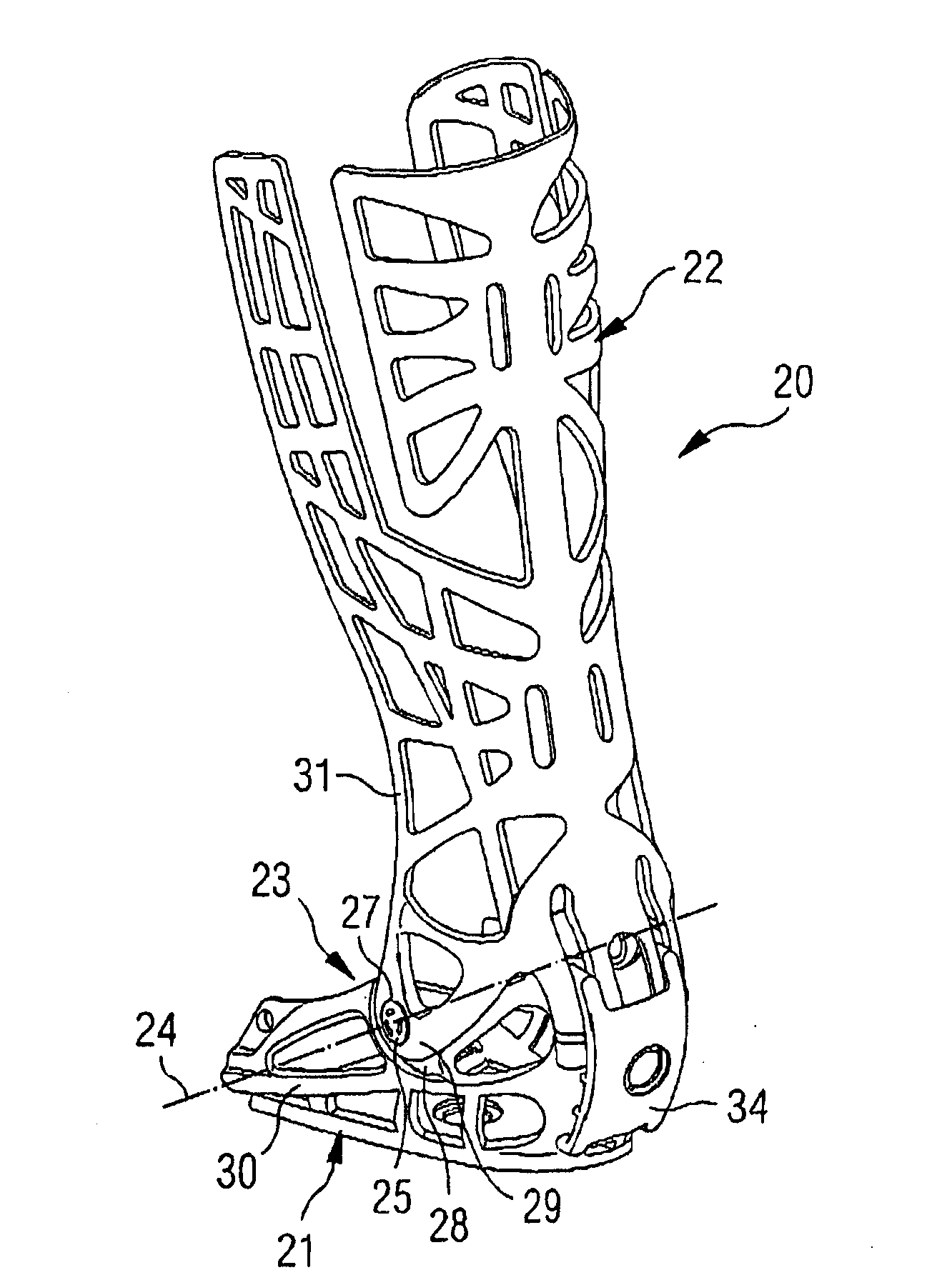
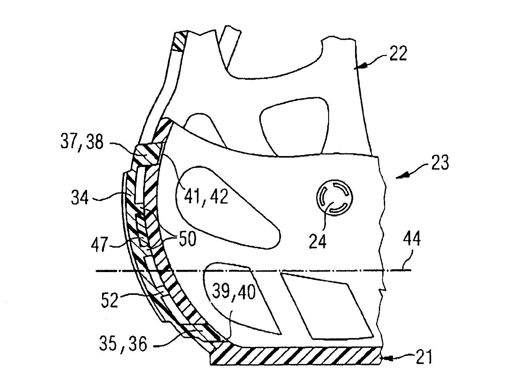
[0082] In rear side view ( figure 2 shown), a shell structure 20, which is composed of a foot plate shell 21 and a lower leg shell 22, the two are connected to each other through a joint pivot structure 23 with a pivot 24, the joint The pivot structure 23 includes two joint pivots 25, which respectively pass through the accommodating holes 27 through the joint extension pieces 28, 29 of the foot plate shell wall 30 or the joint shell wall 31, and pass through a fastening connection device ( not shown in the figure) and fixed on the joint extension pieces 28,29.

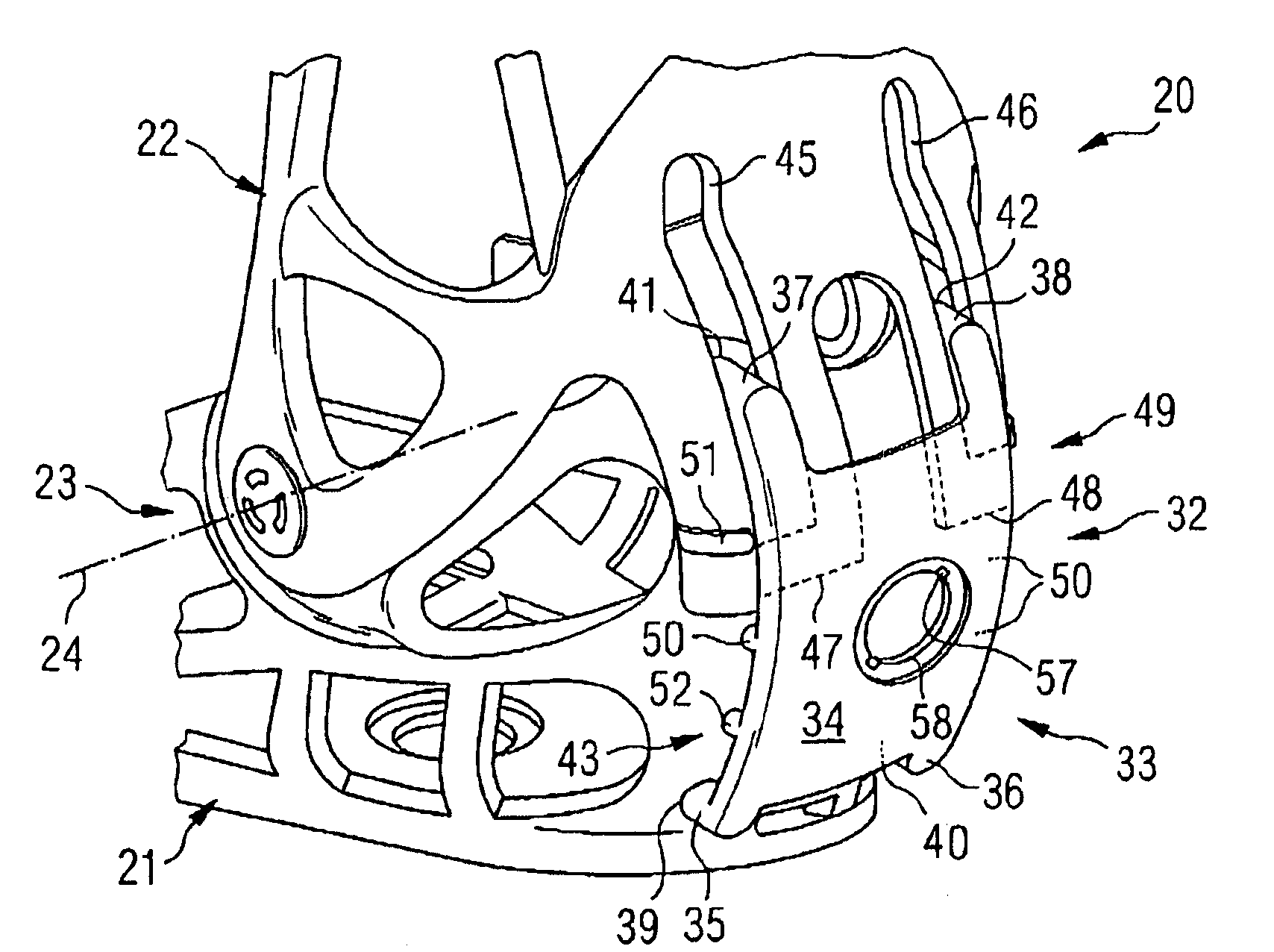
[0083] Such as figure 2 As shown in the enlarged view of the heel portion 32 of the housing structure 20 , a rotational angle adjustment device 33 having a shell-shaped angle adjustment component 34 is disposed on the heel portion 32 . In this embodiment, the angle adjustment assembly 34 includes four engaging devices 35, 36, 37, 38, which are fixed in the positioning grooves 39, 40, 41, 42. These positioning groo...


PUM


Abstract

The invention relates to a casing structure for fixing and receiving a lower leg, in particular to an arrangement for receiving the lower leg in an ankle joint region comprising a foot shell for receiving a foot, and a lower leg shell for receiving the lower leg. The two shells are connected with each other by a joint pivoted mechanism formed by pivots. A rotation angle adjusting device is provided on a heel region between the foot shell and the lower leg shell to control a bending range or position of the foot. The heel region has an overlap region, and the rotation angle adjusting device includes an angle adjusting unit with a meshing unit, a plurality of location grooves disposed on the heel position of the foot shell, and a guide means on a lower leg position of the lower leg shell. In addition, the angle adjusting unit is provided with a locking device for fixing the lower leg shell, characterized in that: the angle adjusting unit slightly extends over the whole height of the heel position of the foot shell so that location grooves are respectively arranged on the lower and the upper edges of the heel position of the foot shell, and at least one meshing unit is meshed into the corresponding location groove.

Description

technical field [0001] The invention relates to a housing structure for fixedly accommodating the calf, especially a foot plate housing for accommodating the sole of the foot and a calf housing for accommodating the calf in the area of ​​the ankle joint. The formed joints are pivotally connected to each other. Furthermore, a rotation angle adjusting device is provided at the heel between the foot plate shell and the calf shell to control the bending range or position of the foot. The heel area has an overlapping area, and the rotation angle adjustment device is provided with an angle adjustment assembly including an engaging device, positioning grooves at the heel position of the foot plate shell, and a guide at the calf position of the calf shell. lead device. In addition, the angle adjustment assembly is provided with a latch device for fixing the foot plate housing. Background technique [0002] According to the aforementioned shell structure for fixedly accommodating ...

Claims


Application Information

Patent Timeline
IPC IPC(8): A61F5/05A61F5/01
CPCA61F5/0127
Inventor A·哈斯勒
Owner OPED
Why Eureka
Try Eureka