Vibration motor

A technology of vibrating motors and brushes, which is applied to electric components, fluids utilizing vibration, electrical components, etc., can solve problems such as defects, falling off or flowing, and deformation of the upper shell 150

Inactive Publication Date: 2003-10-08
SAMSUNG ELECTRO MECHANICS CO LTD
View PDF0 Cites 10 Cited by
  • Summary
  • Abstract
  • Description
  • Claims
  • Application Information

AI Technical Summary

Problems solved by technology

[0017] However, in the vibrating motor provided in the prior art with the above-mentioned structure, the above-mentioned connector 300 is simply fixed on the periphery of the upper case 150 by an adhesive, and it cannot maintain a firm fixed state when the outside is impacted or dropped, and it is easy to dislodge from the upper case 150. Falling off or flowing, and the terminals 310 and 320 protruding from one end of the above-mentioned connector 300 do not have other supporting and fixed structures, so they are easily deformed by the impact force, gradually causing adverse effects

Method used


Image

  • Vibration motor
  • Vibration motor
  • Vibration motor

Examples


Embodiment Construction

[0045] Hereinafter, specific examples of the vibration motor of the present invention will be described in detail with reference to the accompanying drawings.

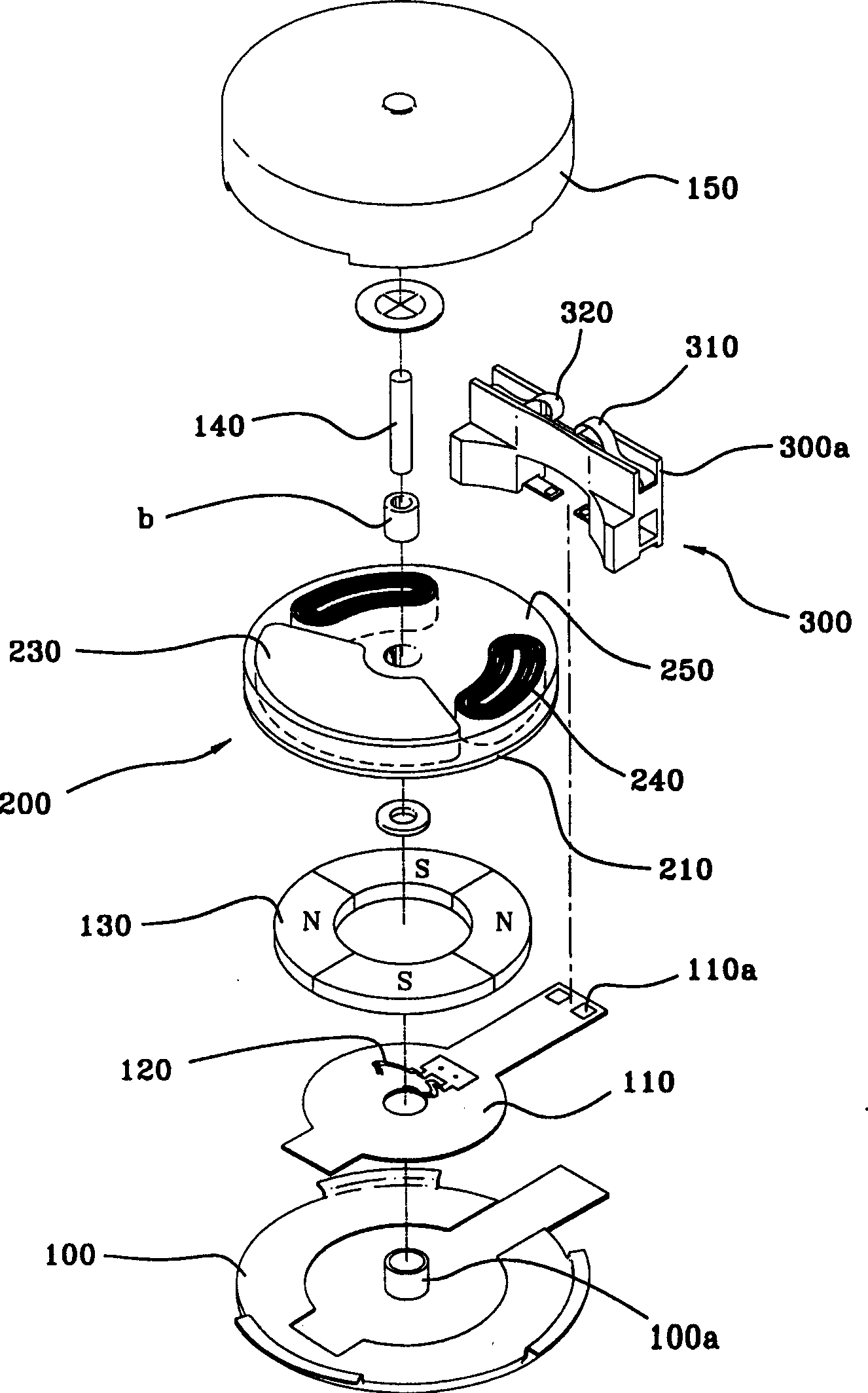
[0046] Figure 5 is an end view of a vibration motor illustrated according to the present invention; Figure 6 for Figure 5Analytical perspective view of the vibrating motor shown in ; Figure 7 and Figure 8 Is a perspective view of a vibration motor illustrated in accordance with the present invention.

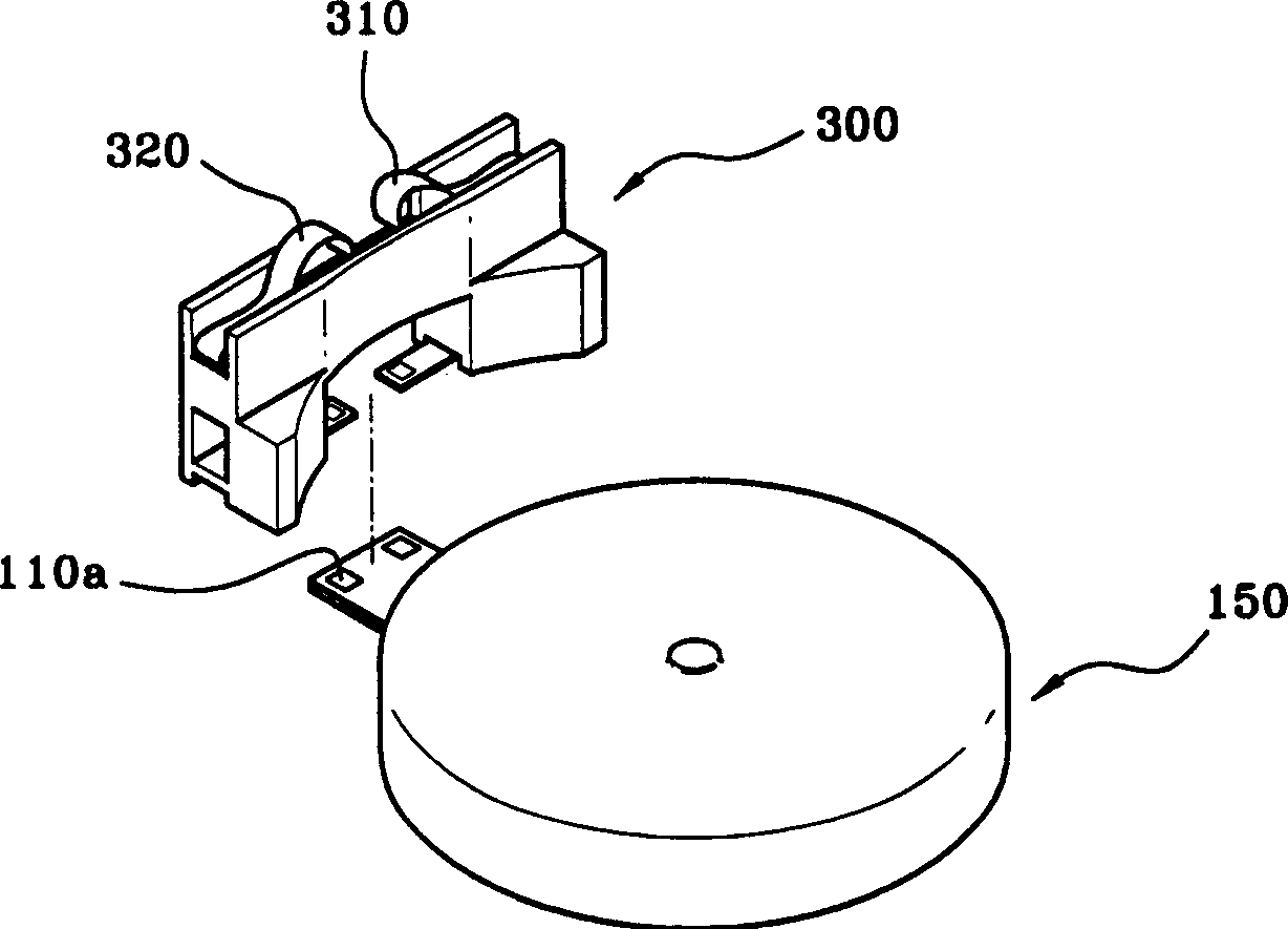
[0047] Figure 9 for illustration Figure 5 Enlarged view of Part "A"; Figure 10 In the vibration motor according to the present invention, the end view of the connector is illustrated; Figure 11 In the vibration motor according to the present invention, a plan view of a connector is shown.

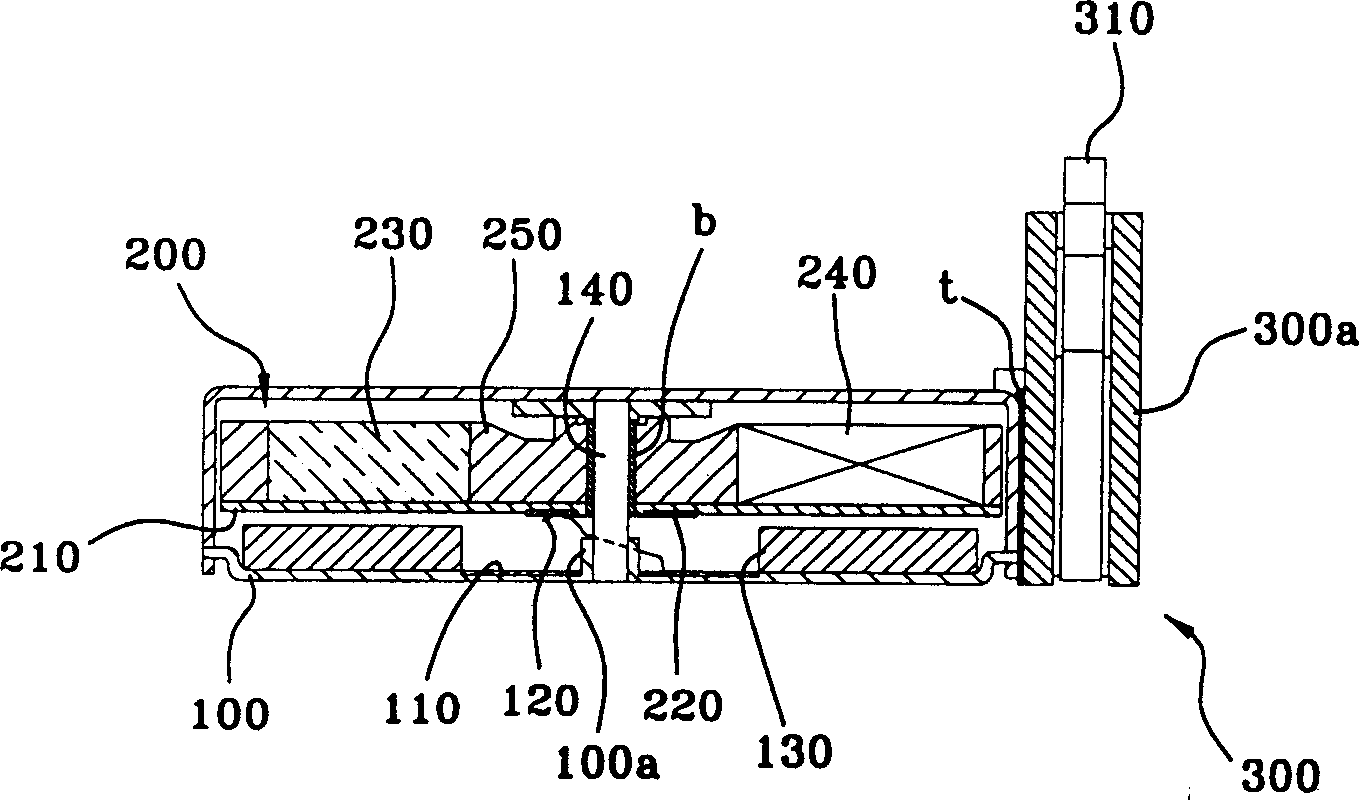
[0048] As mentioned above, the vibration motor is usually composed of a stator, a rotor, and a connector. At this time, the stator is composed of an upper shell 15 and a lower shell 10, as well as a shaft 14, a lower ...


PUM


Abstract

Disclosed is a vibration motor having a connector header coupled to an outer face of a housing via welding to maintain a securely fixed position even under external impact or dropping.

Description

field of invention [0001] The present invention relates to a coin type vibrating motor built in a mobile communication device such as a mobile phone and used as a receiving part through vibration. In particular, it relates to a vibration motor capable of maintaining a firm and fixed state by improving the assemblability of a connector header. Background technique [0002] One of the necessary functions in a general mobile communication terminal is the receiving function. The most frequently used types of reminders for this mail receiving function are sound methods such as ringtones and vibration methods of vibrating machines. If the user selects the mail receiving prompt method in advance, when the message is received, the selected mail receiving prompt mode is activated to enable the user to receive the mail. [0003] Among the above-mentioned receiving types, especially the vibration method is mainly used in places where many people gather, and it is used from the standp...

Claims


Application Information

Patent Timeline
Patent Type & Authority Applications(China)
IPC IPC(8): B06B1/04B06B1/16H02K5/22H02K7/06H02K7/065H02K33/00
CPCH02K7/063H02K5/225H02K7/065H02K33/00
Inventor 梁右锡韩炳宪
Owner SAMSUNG ELECTRO MECHANICS CO LTD
Why Eureka
Try Eureka