Supercharge Your Innovation With Domain-Expert AI Agents!

Needle rod driving mechanism

A driving mechanism and needle bar technology, which is applied to the mechanism of embroidery machines, embroidery machines, sewing machine components, etc., can solve the problems of large space, large space, and increased load.

Inactive Publication Date: 2003-11-26
JUKI CORP
View PDF0 Cites 0 Cited by
  • Summary
  • Abstract
  • Description
  • Claims
  • Application Information

AI Technical Summary

Problems solved by technology

As a result of connecting one fulcrum (the third connection point 111) to three links, the maximum width of the link (the width in the direction of the fulcrum axis) D1 becomes larger, which requires a large space
In particular, in the case of a multi-needle sewing machine such as a double-needle sewing machine, the required space is very large.
[0010] In addition, when the maximum width D1 of the connecting rod increases, the part of the second rod 112 becomes larger, and the Figure 7 In the case of a multi-needle sewing machine such as the illustrated double-needle sewing machine, the width W of the oscillating body 104 is increased to increase the size.
As a result, the load applied to each fulcrum becomes larger, which is especially problematic when the sewing machine is operated at high speed.
[0011] In addition, three connecting rods are connected at one fulcrum, which also increases the cost due to the high precision required for each component.

Method used


Image

  • Needle rod driving mechanism
  • Needle rod driving mechanism
  • Needle rod driving mechanism

Examples


Embodiment Construction

[0022] Hereinafter, embodiments of the present invention will be described with reference to the drawings.

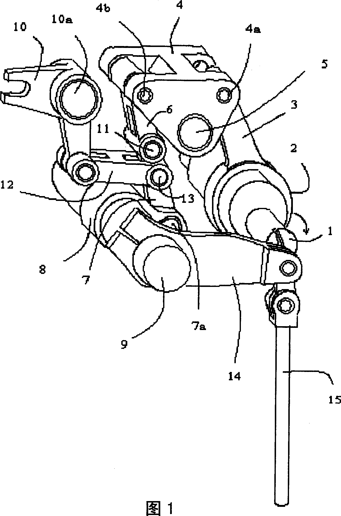
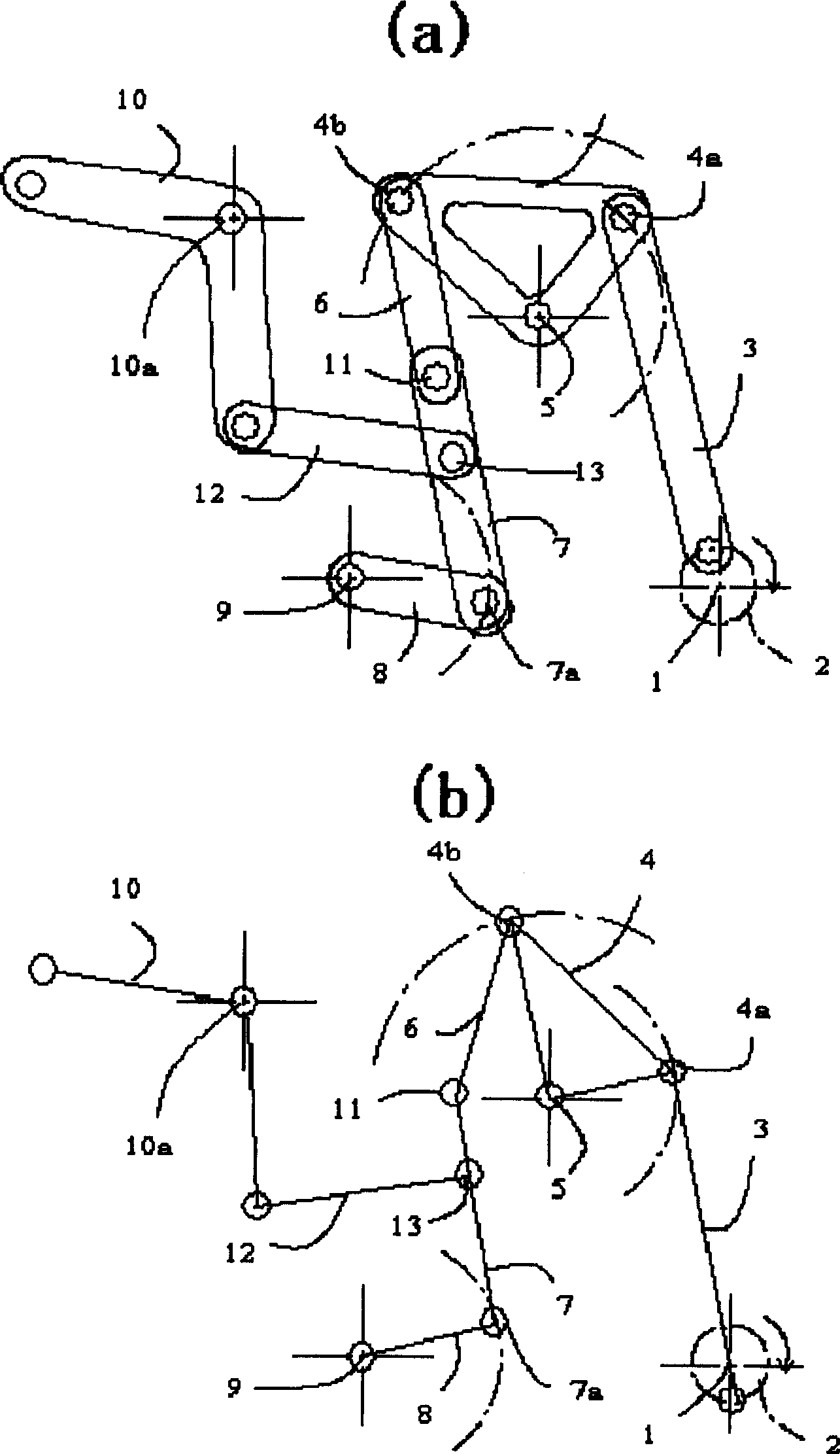
[0023] First, referring to Figure 1 and figure 2 (a) The structure of the needle bar drive mechanism of this embodiment will be described. The needle bar driving mechanism includes a sewing machine main shaft 1 and a needle bar driving shaft 9 rotatably supported on an unshown sewing machine frame, and a support shaft 5 and a lever shaft 10a respectively fixed on the sewing machine frame.

[0024] The eccentric cam 2 is fixed on the main shaft 1 of the sewing machine. The rocking arm 3 that one end is installed on this eccentric cam 2 with a shaft, rocks along with the movement of the sewing machine main shaft 1 . The middle part of the rocking body 4 is rockably supported on a support shaft 5 supported on the sewing machine frame. The rocking body 4 is rotatably connected to the other end of the rocking arm 3 at the first connecting point 4a at one end thereof, and...


PUM


Abstract

To provide a driving mechanism of a needle bar which enables the reduction of a space. The mechanism is provided with a swing arm of which one end is fitted axially to an eccentric cam provided at a main shaft, a support shaft supported by a machine frame, a swing body of which the intermediate part is supported swingably by the support shaft and which is connected rotatably to the other end of the swing arm at a first connecting point at one end, a first connecting arm of which one end is connected rotatably to a second connecting point at the other end of the swing body and which has a length equal to the distance from the support shaft and the second connecting point, a second connecting arm of which one end is connected rotatably to a third connecting point at the other end of the first connecting arm, a first rod of which one end is made rotatably at a fourth connecting point at the other end of the second connecting arm and of which the other end is fixed to a needle bar driving shaft, a second rod which is connected to the second connecting arm at a fifth connecting point in the middle of the third connecting point and the fourth connecting point, and a moving means which moves the third connecting point to a needle bar stop position on the axis of the support shaft and to a position where a needle bar moves up and down and which is off the axis.

Description

technical field [0001] The invention relates to a needle bar drive mechanism capable of maintaining a needle bar in a state of being able to move up and down or in a stopped state. Background technique [0002] The sewing machine has a rotatable main shaft and a needle bar drive mechanism connected to the main shaft and used to convert the rotational movement of the main shaft into the up and down movement of the needle bar. When sewing, the main shaft of the sewing machine is turned to make the needle bar move up and down. Therefore, during the rotation of the main shaft of the sewing machine, the needle bar usually moves up and down. However, depending on the sewing machine, it is sometimes necessary to stop the vertical movement of the needle bar while the main shaft is rotating. For example, when sewing with a two-needle sewing machine, one of the needles is often stopped while the other needle is used to form a stitch. Or such as an embroidery sewing machine, when mov...

Claims


Application Information

Patent Timeline
IPC IPC(8): D05B55/16D05B55/14D05C11/06
CPCB29C33/202B29C44/58
Inventor 后藤圣司
Owner JUKI CORP
Features
  • R&D
  • Intellectual Property
  • Life Sciences
  • Materials
  • Tech Scout
  • Unparalleled Data Quality
  • Higher Quality Content
  • 60% Fewer Hallucinations
Learn More