Drawer cabinet locking apparatus

A technology of drawer cabinets and buckle locks, which is applied in the direction of building locks, building fastening devices, wing leaf fastening devices, etc., and can solve problems such as inability to draw out

Inactive Publication Date: 2003-12-31
姜方冰
View PDF0 Cites 6 Cited by
  • Summary
  • Abstract
  • Description
  • Claims
  • Application Information

AI Technical Summary

Problems solved by technology

[0003] In order to overcome the above disadvantages of the prior art, the present invention provides a drawer lock device. The technical problem to be solved is that when all the drawers of the multi-drawer cabinet are in the locked state, as long as one of the

Method used


Image

  • Drawer cabinet locking apparatus
  • Drawer cabinet locking apparatus
  • Drawer cabinet locking apparatus

Examples


Embodiment Construction

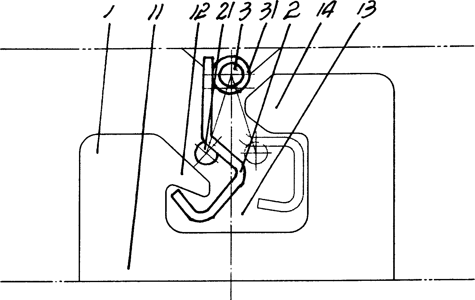
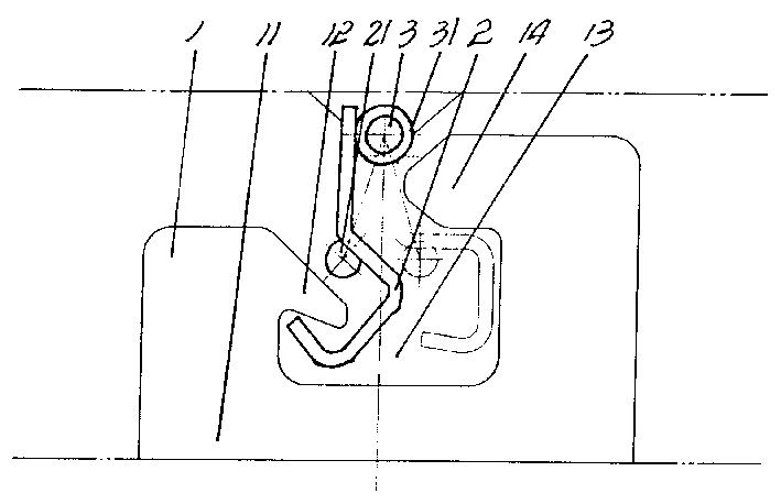
[0008] refer to Figure 1~2 The drawer lock device of this embodiment of the present invention has a shaft (3) whose length is adapted to the height of the back of the drawer and which is cut from a steel cylindrical profile, and the shaft (3) is vertically fixed It is installed on the inner side of the cabinet and between the lower crosspieces corresponding to the reversing block of the total locking device. The C-shaped buckle (1) is stamped and formed by ordinary steel plate at one time, and its bottom end surface, namely the bottom of the groove (11), is respectively fixed on the corresponding shaft (3) on the bottom surface of the inner side plate of each drawer. The C-shaped buckle (1) There is a buckle groove (13) formed by the buckle arm (12) and the buckle arm (14) at its two ends, wherein the outer edge of the buckle arm (12) and the inner edge of the buckle arm (14) are parallel to each other and form an entry Groove channel, clip a buckle hook (2) formed by cold be...


PUM


Abstract

The drawer chest locking device is used to lock drawers in a chest. The locking device includes one shaft rod installed between the upper and lower beams in the back of the chest, C-shaped buckle pieces installed on the side walls of all the drawer, and S-shaped buckle hooks inside the slots of the buckle pieces and connected to the shaft rod. All the said parts constitute a locking mechanism to ensure the safety of the chest.

Description

technical field [0001] The invention belongs to the technical field of special drawer locks for multiple drawers Background technique [0002] The locking mechanism of the known multi-drawer chest of drawers mostly adopts a lock control, which can lock multiple drawers at the same time and open them at the same time. One of the disadvantages of this locking method is that when multiple drawers are opened at the same time or multiple drawers are opened one by one without closing any of the drawers, due to the heavy load in the drawers, the drawers will often appear empty, the center of gravity will shift, and the drawers will turn over. serious consequences of falling. Contents of the invention [0003] In order to overcome the above disadvantages of the prior art, the present invention provides a drawer lock device. The technical problem to be solved is that when all the drawers of the multi-drawer cabinet are in the locked state, as long as one of the drawers is pulled o...

Claims


Application Information

Patent Timeline
IPC IPC(8): E05B65/463E05C19/02E05C19/10
Inventor 姜方冰
Owner 姜方冰
Why Eureka
Try Eureka