Trajectory variable low limb rehabilitation training chair

A training chair and variable technology, applied in passive exercise equipment, physical therapy and other directions, can solve the problems of single elliptical trajectory, unable to adjust the leg length and posture of patients in the rehabilitation cycle, and achieve the effect of avoiding stretching injuries and saving space.

Pending Publication Date: 2019-12-03
HARBIN UNIV OF SCI & TECH
View PDF2 Cites 1 Cited by
  • Summary
  • Abstract
  • Description
  • Claims
  • Application Information

AI Technical Summary

Problems solved by technology

The lower limb rehabilitation training device is more in line with the normal gait of people and has a better rehabilitation effect, but the elliptical trajectory is relatively simple and cannot be adjusted according to the patient's rehabilitation cycle and the patient's leg length

Method used


Image

  • Trajectory variable low limb rehabilitation training chair
  • Trajectory variable low limb rehabilitation training chair
  • Trajectory variable low limb rehabilitation training chair

Examples


specific Embodiment approach 1

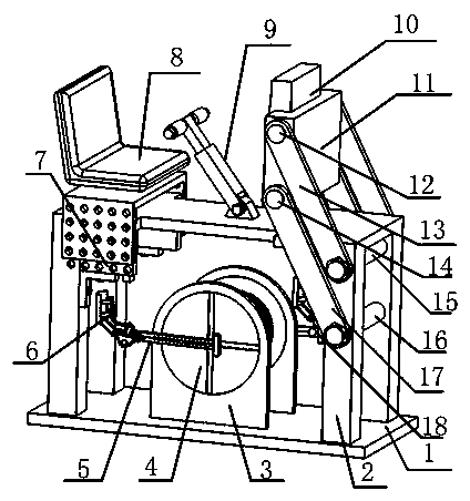
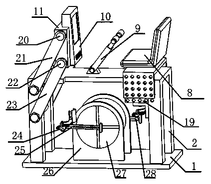
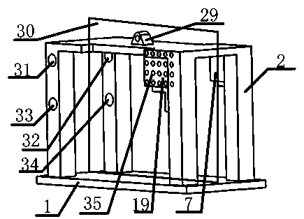
[0033] Combine below figure 1 , 2 , 3, 4, 5, 6, 7, 8, and 9 illustrate this embodiment. The present invention relates to the field of rehabilitation equipment, more specifically, a lower limb rehabilitation equipment with multiple elliptical trajectory motions, including 1. a base plate, 2. a load-bearing frame, 3. Turntable fixed frame I, 4. Cross slide rail turntable I, 5. Track adjustment mechanism I, 6. Ankle fixation mechanism I, 7. Limit plate I, 8. Seat lifting mechanism, 9. Patient hand holding mechanism, 10. Operation panel, 11. Operation panel fixing frame, 19. Limiting plate II, 24. Ankle fixing mechanism II, 25. Track adjustment mechanism II, 26. Turntable fixing frame II, 27. Cross slide rail turntable II, 38. Drive motor, 40. large gear, 42. small gear, the device has a simple structure, and the device can help people perform leg rehabilitation training through the movement of the ankle fixing mechanism. According to the patient's height and leg length, the sea...

specific Embodiment approach 2

[0035] Combine below figure 1 , 2 , 3, 4, 5, 6, 7, 8, 9 illustrate this embodiment, and this embodiment further explains Embodiment 1, and the trajectory adjustment structure I5 ​​includes two long rods I5-11 and rods with semicircular holes. II5-5 place the porous rod 45 formed symmetrically, fix the limit slider I36 and the limit slider II37 connected to the cross slide turntable I4 in the small hole of the porous rod, and use the clamping frame I5-2 Fix the relative position of the long rod I5-11 and the long rod II5-5 with the clamping frame II5-14, when the cross slide rail turntable I4 rotates, the track of the end of the porous rod 45 is an ellipse, and the short axis I5-1 passes through in turn Clamping frame I5-2, spring I5-12, long rod I5-11, long rod II5-5, spring II5-4, clamping frame I5-2, the two ends of the short shaft I5-1 with threads are respectively connected to the nut I5-13 cooperates with the nut II5-3 to fix the relative position of the short axis I5-1...


PUM


Abstract

The present invention discloses a trajectory variable low limb rehabilitation training device. A seat lifting mechanism is attached to a bearing frame and adjustment of seat lifting and lowering is realized by changing relative positions of a small hole in the seat and a small hole fixed in the bearing frame; a trajectory adjusting rod is fixed on two limiting slide blocks and relative positions of rotation of a rotary disk and the two limiting slide blocks on the rod are used to realize change of trajectory of a rod rear end; an ankle fixing mechanism connected with the rod rear end is used to fix relative positions of soles and ankles of a patient, so that damages caused by relative rotary stretching of the ankle parts of the patient are prevented in a rehabilitation training process; and a parallelogram mechanism is used to connect an operating panel on the bearing frame through two corresponding rods, so that the operating panel and the bearing frame are in a fixed angle all the time and the patients are more convenient to use the operating panel. The relative positions of the sliding blocks on the rod can be automatically adjusted according to rehabilitation state of the patients, thereby changing motion trajectory of a kickstand connected with the rod rear end.

Description

technical field [0001] The invention belongs to the field of rehabilitation equipment, in particular to rehabilitation training for patients' lower limbs. Background technique [0002] (1) According to relevant surveys, there are 1.2-1.5 million new stroke cases in my country every year, and about 75% of the survivors are disabled and lose the ability to walk. In addition, diseases that cause lower limb paralysis include spinal cord injury and trauma, such as lower limb joint disease, spinal muscular atrophy, multiple sclerosis, etc. Impaired lower extremity mobility can lead to serious complications. Long-term bed rest of the patient will lead to obstruction of venous blood return of the lower limbs, poor blood supply of the lower limb tissues, etc., which will cause the decline of the physiological function of the lower limbs, and severe cases will lead to disuse syndrome. [0003] (2) Traditional studies have shown that rehabilitation training can accelerate the blood f...

Claims


Application Information

Patent Timeline
Patent Type & Authority Applications(China)
IPC IPC(8): A61H1/02
CPCA61H1/0214A61H1/0237A61H2201/1215A61H2205/10
Inventor 张永德高英博姜金刚代雪松胡逸锋赵梓汐
Owner HARBIN UNIV OF SCI & TECH
Why Eureka
Try Eureka