Supercharge Your Innovation With Domain-Expert AI Agents!

Workpiece holding device

A technology for holding devices and workpieces, applied in the direction of work accessories, manufacturing tools, stone processing tools, etc., can solve the problems of enlarged diameter, deterioration of perforation accuracy, and increase of slack.

Inactive Publication Date: 2004-05-05
UHT CORP
View PDF0 Cites 3 Cited by
  • Summary
  • Abstract
  • Description
  • Claims
  • Application Information

AI Technical Summary

Problems solved by technology

[0009] However, although the joint method (No. A) applies tension without causing wrinkles and slack on the workpiece, and engages the positioning hole with the positioning pin, the workpiece part between the joint parts is not fixed, so it is easy to cause tension on the part of the workpiece between the joint parts. The slack over time increases the amount of slack in proportion to the size of the workpiece to be pierced, and there is a problem that the piercing accuracy deteriorates.
[0010] In the case where the workpiece holder is clamped by the collet and the moving mechanism is controlled to move along the X and Y axis directions to perform piercing processing on the required part of the workpiece, the control action of the workpiece holder is carried out at high speed, so each time the workpiece stops. Large inertial force, the diameter of the positioning hole that doubles as the reference hole is affected by the inertial force, and there are problems of loosening and deterioration of piercing accuracy.

Method used


Image

  • Workpiece holding device
  • Workpiece holding device
  • Workpiece holding device

Examples


Embodiment Construction

[0080] Embodiments of the workpiece holding device according to the invention will be described below. Figure 1~ Figure 5 The first embodiment is shown, and Fig. 6 to Fig. 11 show the second embodiment, Figure 12 ~ Fig. 15 shows the third embodiment, Fig. 16 shows the fourth embodiment, Fig. 17 ~ Fig. 21 shows the fifth embodiment, Figure 22 ~ Fig. 25 shows the sixth embodiment, Fig. 26 and Fig. 27 show the seventh embodiment, Fig. 28 and Fig. 29 show the eighth embodiment, Figure 30 ~ Figure 34 Showing the ninth embodiment, Figure 35 and Figure 36 A tenth embodiment is shown.

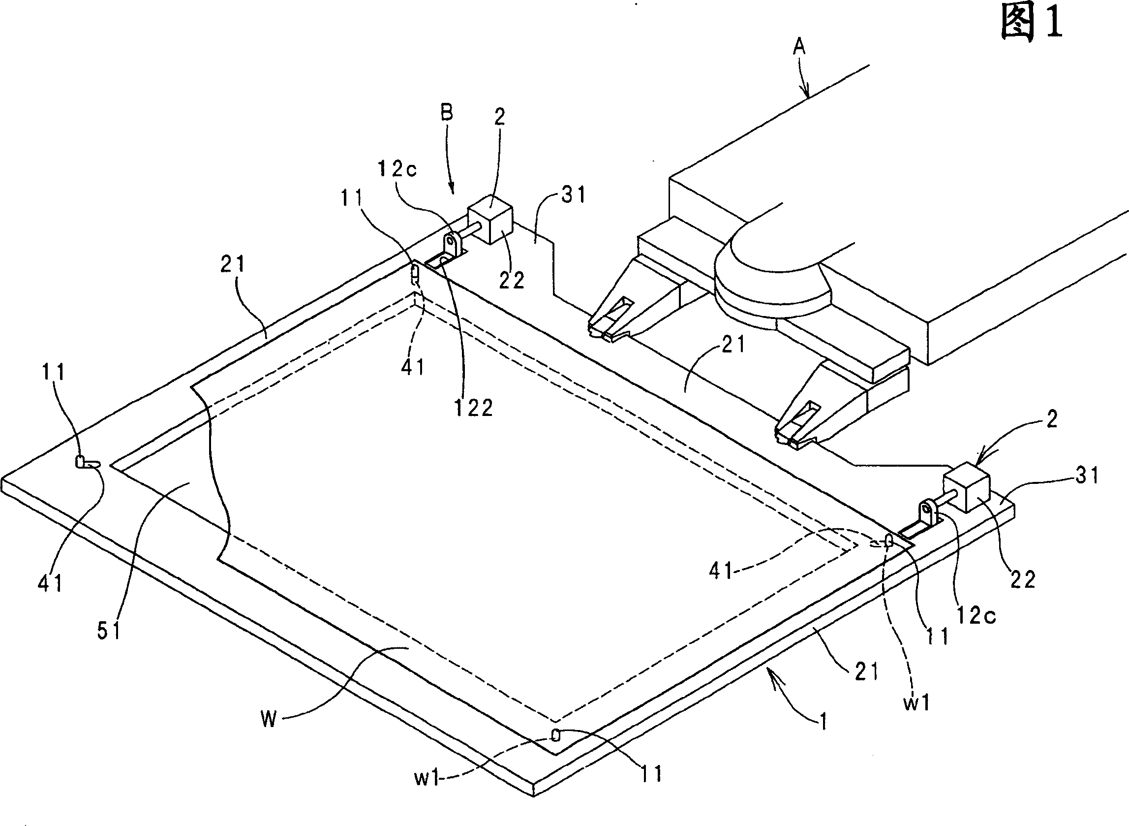
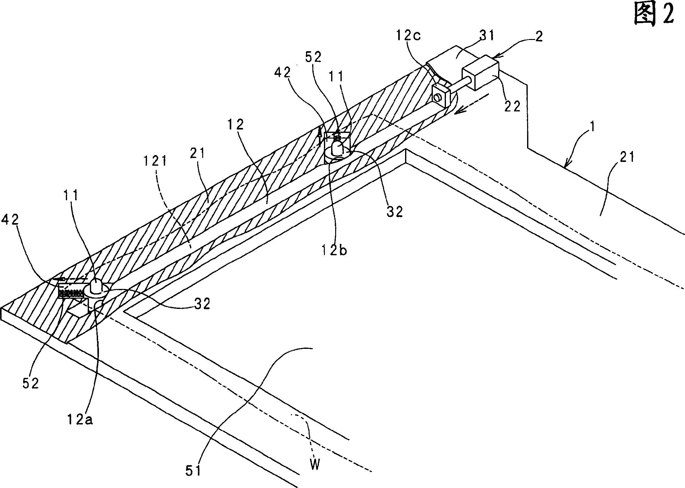
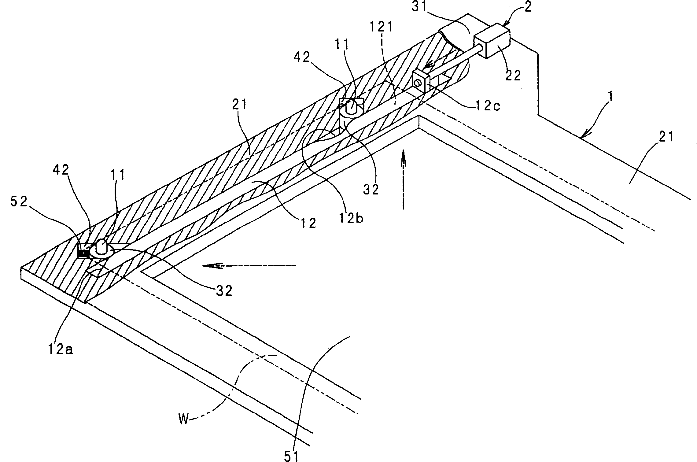
[0081] First, the first embodiment will be described. Symbol 1 is a workpiece support, and symbol B is a tension applying mechanism provided on the workpiece support 1 .

[0082] This tension applying mechanism B includes positioning pins 11 provided at positions corresponding to the four corners of the workpiece W so as to be movable in the diagonal direction of the workpiece W in the work...


PUM


Abstract

To hold a workpiece by a work holder without permitting wrinkles or loosening.In the work holer 1, positioning pins 11 are provided at corresponding positions to four corners of the workpiece W to be movable in diagonal directions of the workpiece W, and on the work holder 1, a pin moving drive 2 to move the positioning pin 11 for prescribed quantity outward in the diagonal direction of the workpiece W for providing prescribed tension to it is provided. Otherwise, a clamp body to releasably hold the workpiece is provided at a desired position of the work holder, and a clamp moving drive to move the clamp body for prescribed quantity for providing prescribed tension to the workpiece is provided.C)2004,JPO.

Description

technical field [0001] The present invention relates to a workpiece holding device that holds workpieces such as ceramic unprocessed sheets, flexible wiring boards, flexible films, metal foils and other thin plate-like objects reinforced by lining films, and conveys them to the punching part. Hold the workpiece until the desired piercing process is performed. Background technique [0002] Flexible workpieces such as ceramic green sheets reinforced with a liner film, flexible wiring boards, flexible films, thin plates such as metal foils, etc. are held by a frame-shaped jig in plan view called a workpiece holder. [0003] The workpiece support is clamped by the chuck at the front end of the moving mechanism and moves along the X and Y axis directions on the machine table under control, and the required perforation processing of the workpiece is performed on the perforating part. [0004] Examples of the method of holding the workpiece on the workpiece holder include a method...

Claims


Application Information

Patent Timeline
IPC IPC(8): B28D1/14B28D7/04
Inventor 柿本武士北原广之
Owner UHT CORP
Features
  • R&D
  • Intellectual Property
  • Life Sciences
  • Materials
  • Tech Scout
  • Unparalleled Data Quality
  • Higher Quality Content
  • 60% Fewer Hallucinations
Learn More