
Electric drop bolt with slidable drive mechanism

A latch and joint technology, applied in the field of safety locks, can solve problems such as jamming and asynchronous driving mechanisms

Active Publication Date: 2004-10-20
ASSA ABLOY AUSTRALIA PTY LTD
View PDF0 Cites 21 Cited by
  • Summary
  • Abstract
  • Description
  • Claims
  • Application Information

AI Technical Summary

Problems solved by technology

This construction requires excessive depth in the shell to accommodate the pivoting of the box
Also, the drive mechanism may get out of sync and jam during disengagement of the roller nut from the latch

Method used


Image

  • Electric drop bolt with slidable drive mechanism
  • Electric drop bolt with slidable drive mechanism
  • Electric drop bolt with slidable drive mechanism

Examples


Embodiment Construction

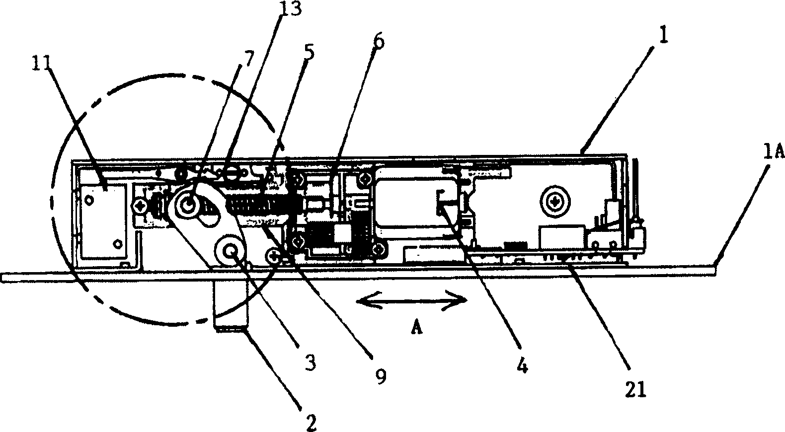
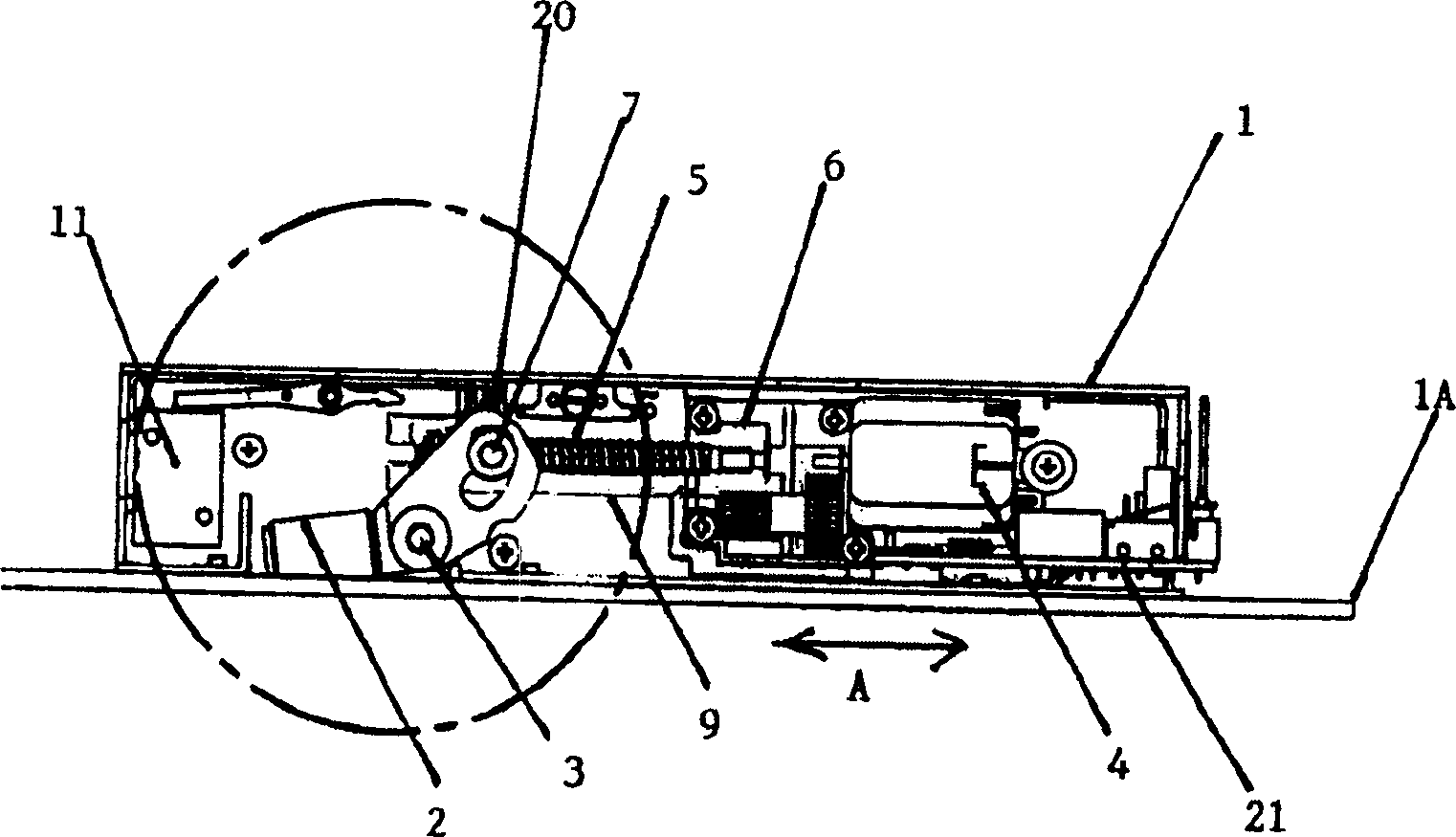
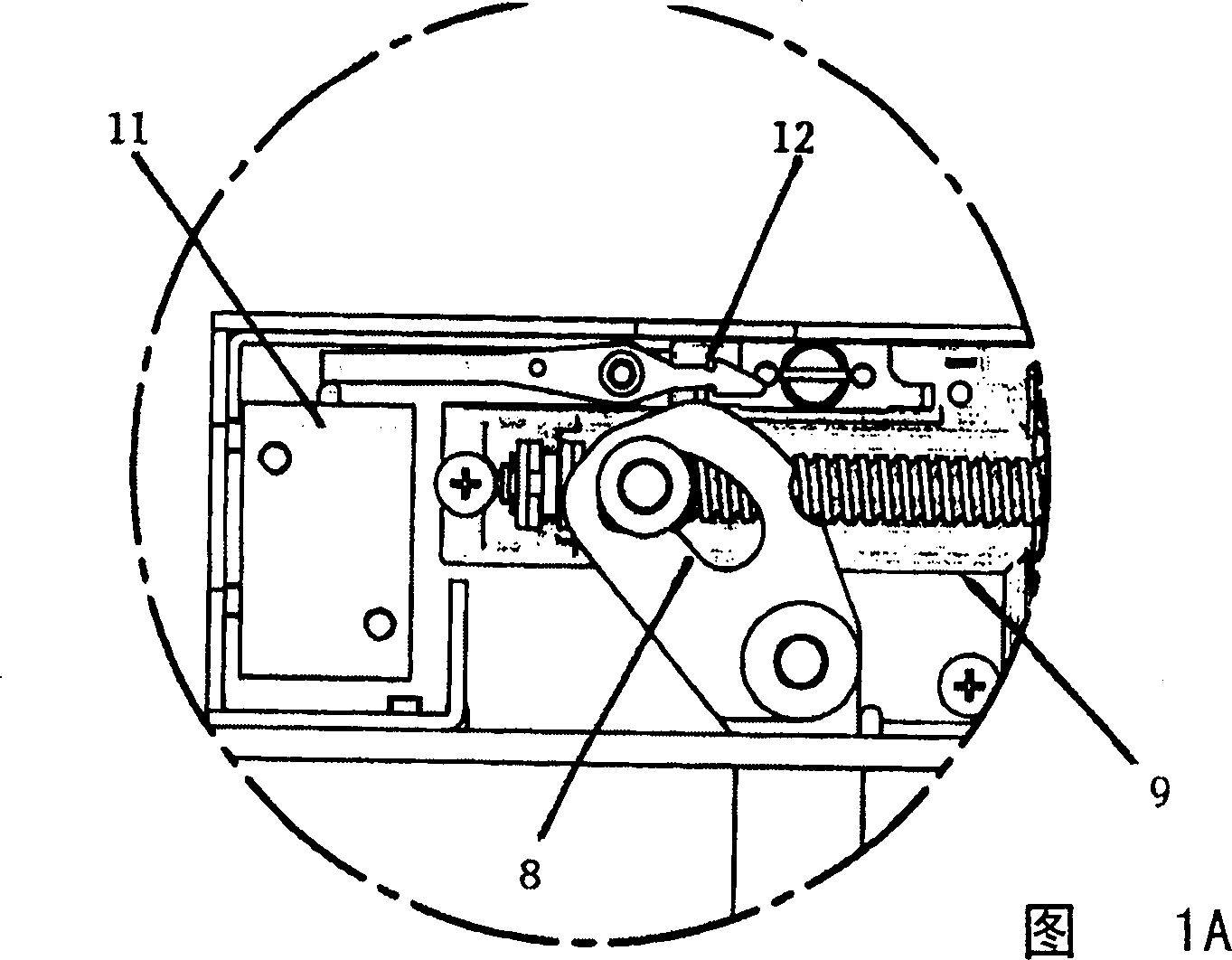
[0015] see first figure 1 , shows an electric lock comprising a casing 1 suitable for being installed in a door frame with an outward facing panel 1A. The housing has a latch 2 which is pivotable about a pin 3 so that it can be figure 1 Movement between a locked configuration shown in and an unlocked configuration in which the latch 2 protrudes out of the frame and in the unlocked configuration the latch 2 is substantially inside the housing. The mechanical drive assembly for the latch consists of an electric motor 4 rotating a screw shaft 5 via a reduction gear 6 . A roller nut 7 is mounted on the screw shaft 5, and when said shaft is turned by the motor, the roller nut 7 moves along the length of the shaft. The roller nut 7 in turn engages a closed cam surface 8 formed as part of the latch 2 . When the mechanical drive assembly is in figure 1 In the normal operating position shown in , the roller nut moves to figure 1 The left end or the right end (not shown) of the scr...


PUM


Abstract

There is an electric motor driven drop bolt having a housing which in use is mounted into a doorway frame and has the bolt pivotal therein by a mechanical drive set in a cage disposed at an operative position. The bolt is pivotal between a locking configuration where the bolt extends outward of the housing to engage in an aperture associated with a door within the frame and an unlocked configuration where the bolt is withdrawn to clear the aperture. The mechanical drive includes a screw shaft rotatable by the electric motor to move a roller nut along the length of the shaft whilst engaging a cam surface on the bolt. To obtain fail safe operation of the drop bolt the cage is slidable in the housing from the operative position to a disengaged position so that the bolt is movable from the locking configuration to the unlocked configuration without operation of the mechanical drive.

Description

technical field [0001] The present invention relates to safety locks. More particularly, although not exclusively, it discloses an improved electric motor driven swing latch including a user selectable power open or power lock transition mode. Background technique [0002] The purpose of the swing deadbolt is to provide a concealed lock for a door or movable barrier. In prior art arrangements, a solenoid is used to move the deadbolt axially out of the door frame and into a strike plate mounted in the door rim. The strike plate has an aperture sized to receive the latch axially to effectively lock the door once it is in place. This device is usually used in places where both safety and concealment are required when locking the door. [0003] However, there are a number of problems with these devices currently in use. If there is any misalignment of the door in the frame, the deadbolt will hit the strike plate instead of seating in the hole. Although with some systems the...

Claims


Application Information

Patent Timeline
Patent Type & Authority Applications(China)
IPC IPC(8): E05B47/02E05B15/02E05B17/00E05B47/00E05B47/06E05B63/00
CPCE05B47/0002Y10T292/1079E05B2047/0076E05B17/0025E05B63/0073Y10T292/1021E05B47/0012E05B47/0607E05B15/0205E05B63/0013E05B2047/0068Y10T292/1082E05B2047/0023E05B47/023B42D3/18B42D15/0053G09F23/10B42F5/00B42P2241/10
Inventor G·J·卢克
Owner ASSA ABLOY AUSTRALIA PTY LTD
Learn More