
Electroluminescence device

A technology of electroluminescent devices and electroluminescent elements, which is applied in the direction of electroluminescent light sources, electric light sources, lighting devices, etc., and can solve the problems of reducing the light output efficiency of electroluminescent devices, etc.

Inactive Publication Date: 2005-06-15
TOYOTA IND CORP
View PDF1 Cites 1 Cited by
  • Summary
  • Abstract
  • Description
  • Claims
  • Application Information

AI Technical Summary

Problems solved by technology

This reduces the light output efficiency of the electroluminescent device

Method used


Image

  • Electroluminescence device

Examples


Embodiment Construction

[0022] DETAILED DESCRIPTION OF THE PREFERRED EMBODIMENT

[0023] As used herein, the term "transparent" refers to the property of transmitting all or part of the light emitted from the electroluminescent device. The transmittance of light in the transparent member is preferably 10% or more, further preferably 50% or more, still more preferably 70% or more. The transmittance can be different or the same for each wavelength.

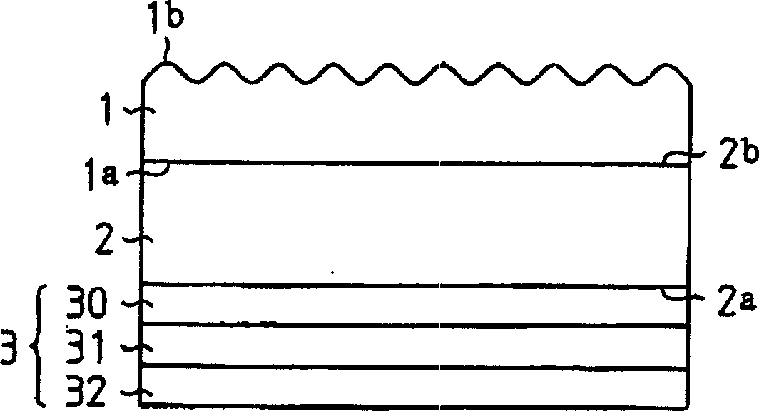
[0024] by reference figure 1 , an organic electroluminescence (EL) device according to a preferred embodiment of the present invention will be described, and the size and magnification of elements in the drawings are different from those of the actual device.

[0025] figure 1 is a cross-sectional view of an organic EL device. Such as figure 1 As shown, in the organic electroluminescent device, a transparent substrate 2 (having a first refractive index) includes a light incident surface 2a and a light emitting surface 2b. Organic EL element 3 is prov...


PUM


Abstract

A bottom emission type electroluminescent device for emitting an increased amount of light in a direction within a range of a predetermined angle with respect to a light incident surface of a transparent substrate. The transparent substrate is sandwiched between the electroluminescent element and the transparent layer. The refractive index of the transparent layer is greater than that of the transparent substrate. Many protrusions and recesses were formed on the top surface of the transparent layer.

Description

[0001] Cross References to Related Applications [0002] This application is based on and claims priority from prior Japanese Patent Application No. 2003-412076 filed on December 10, 2003, the entire contents of which are hereby incorporated by reference. technical background [0003] The invention relates to a bottom emission type electroluminescent device. [0004] Various types of electroluminescent devices have been proposed, such as organic and non-organic electroluminescent (EL) devices. [0005] One example of an electroluminescent device is a bottom emitting device. In a bottom emission type electroluminescent device, light is generated by an electroluminescent element disposed on a transparent substrate. Light passes through the transparent substrate and emerges from the electroluminescent device. However, the light generated by the electroluminescent element can only partially be used in conventional bottom emission type electroluminescent devices. This is due to...

Claims


Application Information

Patent Timeline
Patent Type & Authority Applications(China)
IPC IPC(8): H05B33/02H01L51/50H01L51/52H05B33/10H05B33/20H05B33/22
CPCH10K50/858H05B33/22H05B33/10H10K50/85
Inventor 竹内范仁石川明幸吉田干雄小池秀儿
Owner TOYOTA IND CORP
Learn More