Ventilation arrangement for indoor unit of air-conditioner

An air conditioner indoor unit and indoor unit technology, which is applied in the field of indoor units, can solve problems such as structural limitations of air outlets, and achieve the effect of improving cooling and heating efficiency

Inactive Publication Date: 2005-06-29
LG ELECTRONICS (TIANJIN) APPLIANCES CO LTD
View PDF0 Cites 6 Cited by
  • Summary
  • Abstract
  • Description
  • Claims
  • Application Information

AI Technical Summary

Problems solved by technology

If the cooling or heating efficiency is improved, especially the heating efficiency is improved, the existing air outlet structure is limited

Method used


Image

  • Ventilation arrangement for indoor unit of air-conditioner
  • Ventilation arrangement for indoor unit of air-conditioner
  • Ventilation arrangement for indoor unit of air-conditioner

Examples


Embodiment Construction

[0013] The exhaust structure of the air conditioner indoor unit of the present invention will be described in conjunction with the accompanying drawings and embodiments.

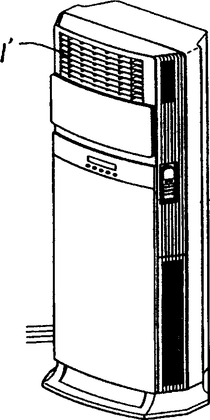
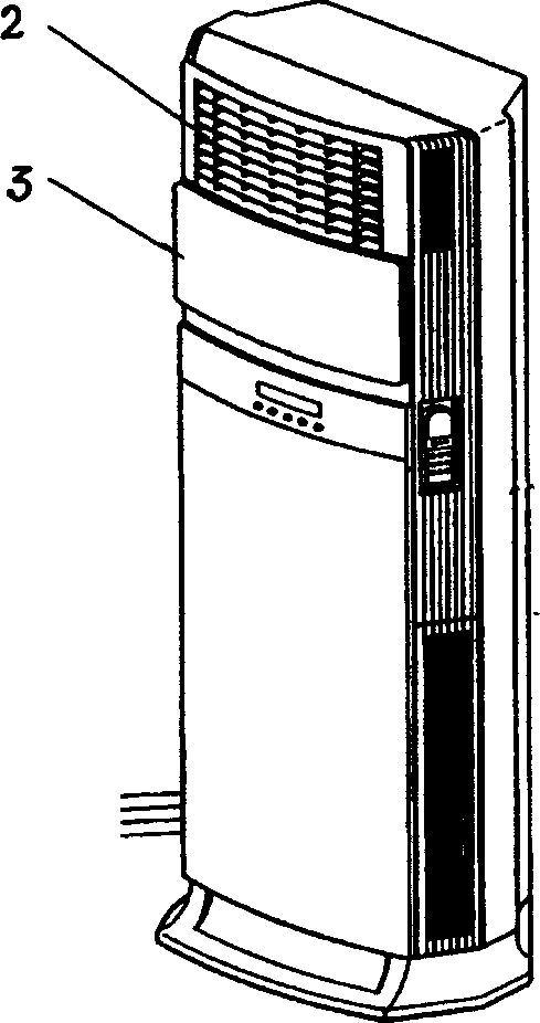
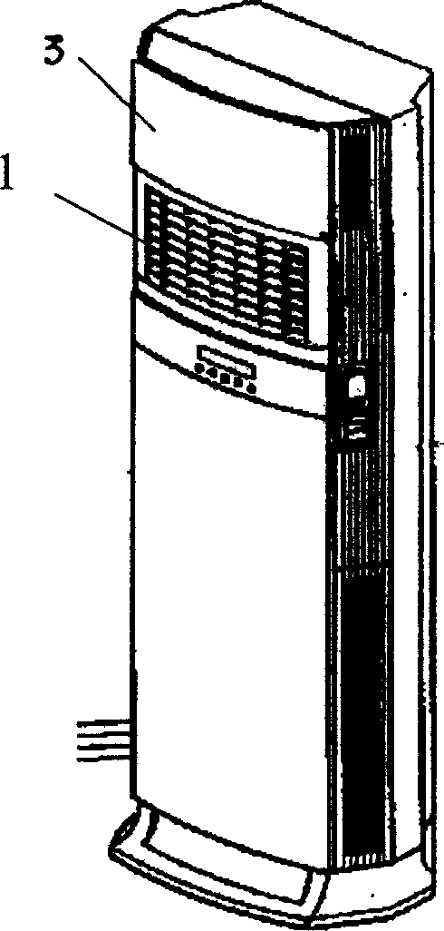
[0014] Such as figure 2 , 3 , 4, the exhaust structure of the indoor unit of the air conditioner of the present invention mainly includes a front shell on the front of the indoor unit, an air outlet, an air outlet moving panel up and down and a driving device for driving the panel are arranged on the upper part, wherein : the air outlet is divided into two parts, the upper and lower air outlets, the upper air outlet is the cold air outlet 2, the lower air outlet is the hot air outlet 1, and one of the air outlets in the air outlet The front is provided with double-layer panels 3, and each layer of panels is connected with the driving device respectively. The two-layer panels 3 are connected as a whole through the slideways arranged between the two-layer panels.

[0015] The air exhaust structure of the i...


PUM


Abstract

The invention provides an exhaust structure of an indoor unit of an air conditioner, which mainly includes a front shell on the front of the indoor unit, an air exhaust port, a panel for moving the exhaust port up and down, and a driving device for driving the panel, wherein: The above air outlet is divided into upper and lower air outlets, the upper air outlet is the cold air outlet, the lower air outlet is the hot air outlet, and the front of one of the air outlets is provided with double air outlets. Layer panels, each of which is connected to the driving device respectively. The two-layer panels are connected as a whole through the slideway arranged between the two-layer panels. The effect of the present invention is that the indoor unit of the air conditioner using this structure can use the upper exhaust port when cooling. When heating, use the lower exhaust. The cooling and heating efficiency is obviously improved, especially the heating efficiency.

Description

technical field [0001] The invention relates to an indoor unit of an air conditioner, in particular to an exhaust structure of an indoor unit of an air conditioner in which air outlets are respectively provided for cooling and heating. Background technique [0002] The general air conditioner is provided with an air outlet 1 ' on the top of the front front shell of the indoor unit, and is provided with upper and lower panels and front and rear panels. When the upper and lower panels are moving up and down, it is either cooling or heating. At this time, the front and rear panels move back and forth. The upper panel of the front shell of the indoor unit is provided with a driving device (not shown) for lifting the upper and lower panels, and a driving device (not shown) for moving the front and rear panels back and forth. [0003] When the upper and lower panels rise, the front and rear panels are controlled by the driving device to move outward, that is, the air outlet is c...

Claims


Application Information

Patent Timeline
Patent Type & Authority Applications(China)
IPC IPC(8): F24F13/10
Inventor 朴世荣朴永哲朴京春李尚昱
Owner LG ELECTRONICS (TIANJIN) APPLIANCES CO LTD
Why Eureka
Try Eureka