
Temperature regulating fan and control method thereof

A technology of temperature regulation and control method, which is applied in heating and ventilation control system, control input related to air characteristics, space heating and ventilation control input, etc. Poor effect and other problems, to achieve high-efficiency cooling and heating efficiency, high cooling efficiency, and high safety

Inactive Publication Date: 2019-10-22
JMATEK (ZHONGSHAN) LTD
View PDF2 Cites 1 Cited by
  • Summary
  • Abstract
  • Description
  • Claims
  • Application Information

AI Technical Summary

Problems solved by technology

[0003] However, the existing temperature-regulating fan mainly absorbs heat energy through the evaporation process of water on the water curtain, that is, under the condition of constant enthalpy, it absorbs the sensible heat of the air to reduce the dry bulb temperature of the air, and the actual cooling effect is poor. , the temperature of the air blown out by the wind wheel is not much different from the room temperature, it is still not cold air, and cannot achieve the purpose of cooling well; in the heating mode, the electric heating tube or PTC material is generally used for auxiliary heating. High energy consumption and poor security

Method used


Image

  • Temperature regulating fan and control method thereof
  • Temperature regulating fan and control method thereof
  • Temperature regulating fan and control method thereof

Examples


Embodiment 1

[0090] ginseng Figure 6 , the temperature regulating fan 100a includes a casing, a wet curtain assembly, and an airflow driving assembly 71a. At least part of the evaporation unit 11a of the wet curtain assembly is made of metal, specifically, the evaporation unit 11a can be metal honeycomb paper, the honeycomb paper has a porous honeycomb array structure, has a higher specific surface area, and significantly increases the evaporation area. Thereby further improving the heat exchange efficiency.

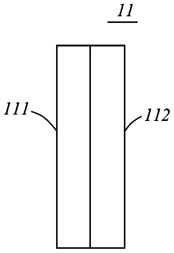
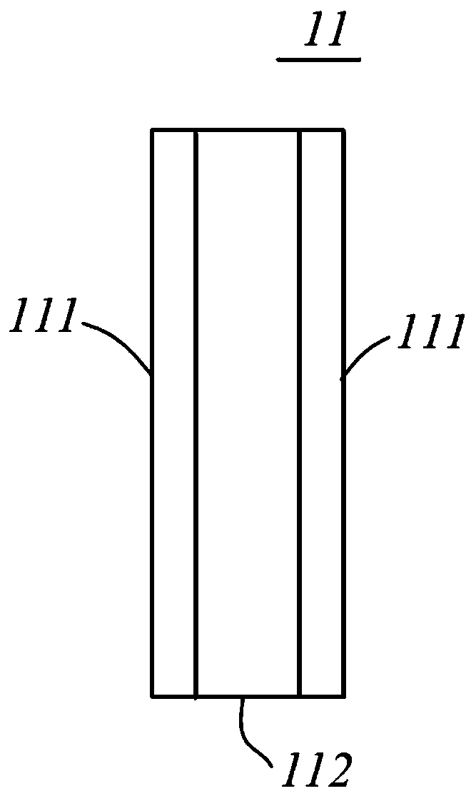
[0091] Similarly, the evaporation unit can also include metal honeycomb paper and paper honeycomb paper composited with each other. The number of composite layers and composite forms of metal honeycomb paper and paper honeycomb paper can be selected according to actual needs, with a three-layer composite structure as the For example, it may be metal honeycomb paper, paper honeycomb paper, and metal honeycomb paper that are sequentially composited; or, paper honeycomb paper, metal h...

Embodiment 2

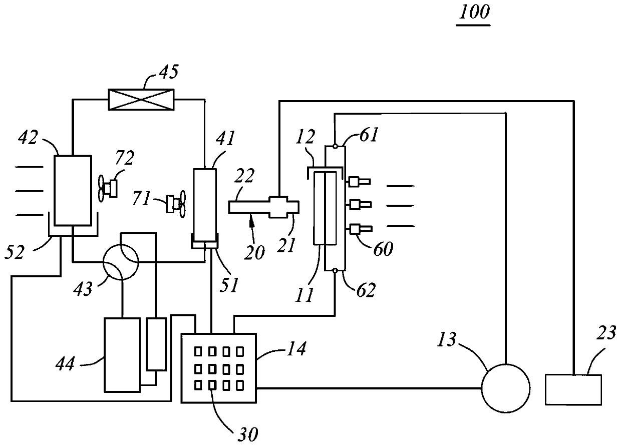
[0094] ginseng Figure 7 and Figure 8 The temperature regulating fan 100b includes a housing, a wet curtain assembly, a vortex cooling assembly 20b, and an airflow driving assembly 71b. The vortex cooling assembly 20b includes a vortex cooling tube, and the vortex cooling tube can at least send the airflow blown out from the cold end 21b or the hot end 22b into the airflow channel in a controlled manner. The number of vortex cooling tubes can be set to one or more according to needs, and the vortex cooling assembly 20b also includes an air compressor 23b in gas communication with the vortex cooling tubes, and the air compressor is used to provide compressed air for the vortex cooling tubes.

[0095] Figure 7 and Figure 8 What is shown is a schematic diagram of cooperation between different ends of the vortex cooling tube and the exhaust channel, and the air flow at the cold end 21b of the vortex cooling tube can make up for the defect of insufficient cooling efficiency o...

Embodiment 3

[0099] ginseng Figure 9 The temperature regulating fan 100c includes a casing, a wet curtain assembly, a temperature control assembly 30c, and an airflow driving assembly 71c. The temperature control assembly 30c cooperates with the water tank 14c to adjust the temperature of the water stored in the water tank 14c. By adjusting the water storage temperature of the water tank 14c, the cooling and heating efficiency of the temperature regulating fan 100c can be further increased. The temperature control assembly 30c here includes a semiconductor refrigerator. The semiconductor refrigerator can be controlled to make its hot end cooperate with the water tank 14c to heat the stored water in the water tank 14c; of water storage.

[0100] That is to say, this embodiment mainly involves the additional temperature control assembly 30c that cooperates with the water tank, and may not involve others.


PUM


Abstract

The invention provides a temperature regulating fan and a control method thereof. The temperature regulating fan and the control method thereof are used to solve the problem of low cooling and heatingefficiency of a temperature regulating fan in the prior art. The temperature regulating fan comprises a shell, a wet curtain assembly, a vertex current refrigeration component and an airflow drivingcomponent, wherein a chamber is formed in the shell, the shell is provided with an air inlet and an air outlet communicating with the chamber, and an airflow channel is formed between the air inlet and the air outlet; the wet curtain assembly includes an evaporation unit arranged in the airflow channel; the vertex current refrigeration component includes a vertex current refrigeration pipe, and the vertex current refrigeration pipe can at least be controlled to feed the airflow blowing from the cold end or the hot end into the airflow channel; and the airflow driving component is used to drivethe airflow entering from the air inlet to the air outlet for blowing out through the airflow channel.

Description

technical field [0001] The invention belongs to the technical field of home appliances, and in particular relates to a temperature-regulating fan and a control method thereof. Background technique [0002] With the improvement of people's living standards, traditional fans have gradually been unable to meet people's daily needs, and fans with temperature regulation functions are gradually being widely used. The existing temperature-regulating fan is usually equipped with a water tank, and a water pump is arranged in the water tank. The water pump draws the normal temperature water in the water tank and transports the water to the top of the water curtain, and evaporates and absorbs heat through the water curtain to reduce the temperature of the surrounding air. Drive the wind wheel to rotate to generate wind, and drive the cooled air to blow out of the box to achieve the purpose of cooling. [0003] However, the existing temperature-regulating fan mainly absorbs heat energy...

Claims


Application Information

Patent Timeline
Patent Type & Authority Applications(China)
IPC IPC(8): F24F5/00F24F11/64F24F11/80F25B9/04F24F110/10F24F110/20
CPCF24F5/0035F24F5/001F24F11/64F24F11/80F25B9/04F24F2110/10F24F2110/20
Inventor 顾迪斯盖博周伙喜
Owner JMATEK (ZHONGSHAN) LTD
Learn More