Thermostatic mixer valve assembled in a cartridge body

A mixer valve, thermostatic technology, used in the field of cocks

Inactive Publication Date: 2005-11-09
南贝尔奥斯卡齐波尼浴室设备公司
View PDF0 Cites 0 Cited by
  • Summary
  • Abstract
  • Description
  • Claims
  • Application Information

AI Technical Summary

Problems solved by technology

[0004] While practical, this known product has the disadvantage of having to assemble the mixer valve components directly within the cock body, which necessitates (machining) machining and shaping the body to accommodate these components properly

Method used


Image

  • Thermostatic mixer valve assembled in a cartridge body
  • Thermostatic mixer valve assembled in a cartridge body
  • Thermostatic mixer valve assembled in a cartridge body

Examples


Embodiment Construction

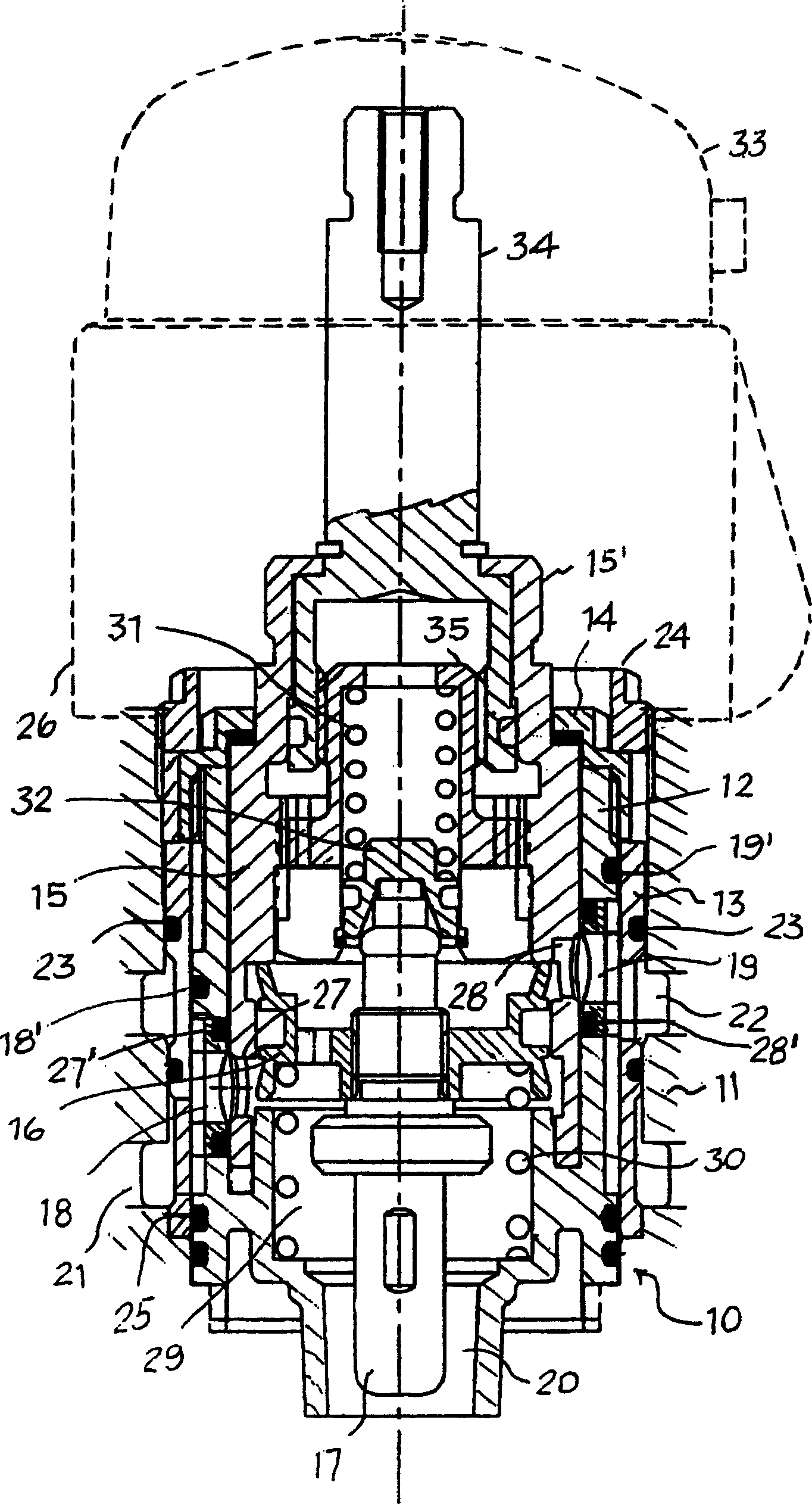
[0017] As shown, the working components of the thermostatic mixer valve of the present application are assembled and held in a barrel 10 inserted as a whole into a cock body 11 .

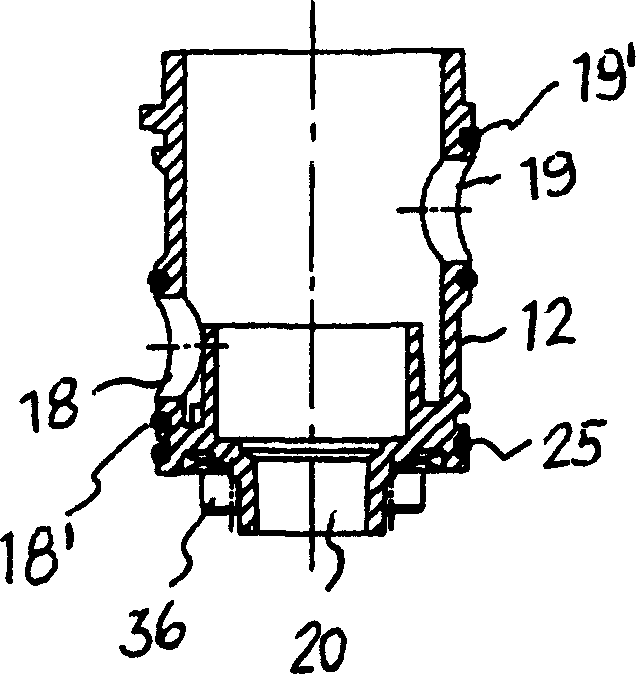
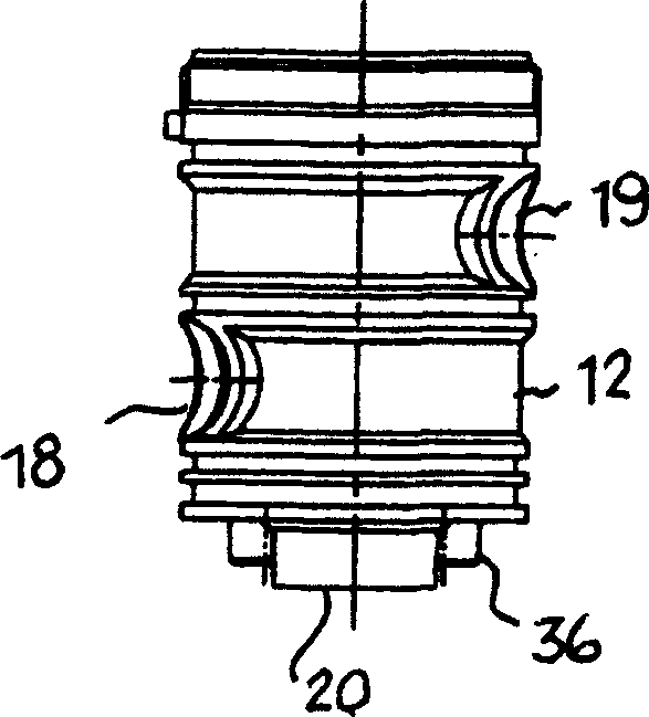
[0018] according to Figure 1-6 product, the barrel 10 consists of a cup-shaped housing 12 that works in conjunction with an outer sleeve 13 and an upper ring nut 14 . The mixer valve unit basically comprises a rotary device 15 for regulating the delivery of water and a mixing element 16 for controlling the temperature of the delivered mixed water. The mixing element 16 operates in conjunction with a thermostatic bulb 17 which is axially movable in response to temperature changes to which the thermostatic bulb 17 is subjected and which is positioned with the thermostatic bulb 17 on the axis of the delivery regulator 15 .

[0019] The cup-shaped housing 12 - likewise the outer casing 13 - has two separate adduction / addition slots 18, 19 for hot and cold water respectively at different heights latera...


PUM


Abstract

The invention concerns a thermostatic mixer valve for hot and cold water, which comprises a rotary delivery regulator device (15), a thermostatic bulb (17) positioned coaxially to said regulator device, and a mixer control device (16) working in conjunction with the thermostatic bulb. The delivery regulator device (15) and the mixer control device (16) with relative thermostatic bulb (17) are assembled and housed ready to operate in a cartridge body (10) inserted as a whole in a tap body which has means of transporting hot and cold water towards a mixer chamber and means of delivering the water towards the user point.

Description

technical field [0001] The present invention relates generally to the field of taps, and more particularly to a hot and cold (water) mixer valve with a thermostatic unit. Background technique [0002] Various solutions for hot and cold mixer valves for sanitation and water supply services are known, including mixers with an associated thermostatic unit to automatically control the temperature of the mixed water delivered valve. [0003] Mixer valves of the type described here consist of parts joined to each other and assembled in a single body, which is the body of the cock in which the mixer valve operates. More specifically, within the body of the cock, said mixer valve comprises a rotary delivery regulator, a thermostatic bulb coaxial with the regulator and a mixing unit responsive to the thermostatic Expansion of the bulb moves axially relative to the delivery adjustment device. The cock body has two transverse holes for the input of hot and cold water respectively le...

Claims


Application Information

Patent Timeline
Patent Type & Authority Applications(China)
IPC IPC(8): G05D23/13
CPCG05D23/1353
Inventor O·南贝尔
Owner 南贝尔奥斯卡齐波尼浴室设备公司
Why Eureka
Try Eureka