
Surgical cutting and stapling device

a surgical and surgical technology, applied in the field of electromechanical surgical systems, can solve the problems of surgical instruments being damaged, orifices of the body being damaged, patient being harmed,

Active Publication Date: 2005-08-25
TYCO HEALTHCARE GRP LP
View PDF99 Cites 1030 Cited by
  • Summary
  • Abstract
  • Description
  • Claims
  • Application Information

AI Technical Summary

Benefits of technology

The present invention relates to a surgical device for cutting and stapling a section of tissue. The device includes a housing with a clamping surface and an anvil moveable relative to the housing. The anvil is mechanically attachable to the housing and moveable between an open position and a closed position. The device also includes a cutting element and a stapling element, both of which are driven by a second driver. The device can be used for both cutting and stapling, and includes a staple cartridge and staple pusher for driving staples. The device is designed to improve the surgical procedure by making it faster and easier to clamp and staple tissue.

Problems solved by technology

One of the problems experienced during surgical procedures of this type is that the orifice of the body may be damaged when the surgical instrument is being introduced, or has been introduced, into the orifice.
This is particularly problematic when the orifice into which the surgical device is being introduced includes fragile tissue that is easily damaged when contacted, e.g., the tissues of the oral cavity.
Another problem experienced during surgical procedures of this type is that the surgical instrument may be damaged when the surgical instrument is being introduced, or has been introduced, into the orifice.
It may be particularly important to avoid damage to the surgical device, since a patient may also be harmed if the surgical device functions improperly.
While significant advances have been made in miniaturizing surgical instruments, conventional surgical instruments are typically not able to be employed within a relatively small orifice or passage of a patient, such an oral passage.
Thus, conventional surgical devices and procedures still risk damage to one or both of the surgical device and the orifice / passage.

Method used


Image

  • Surgical cutting and stapling device
  • Surgical cutting and stapling device
  • Surgical cutting and stapling device

Examples


Embodiment Construction

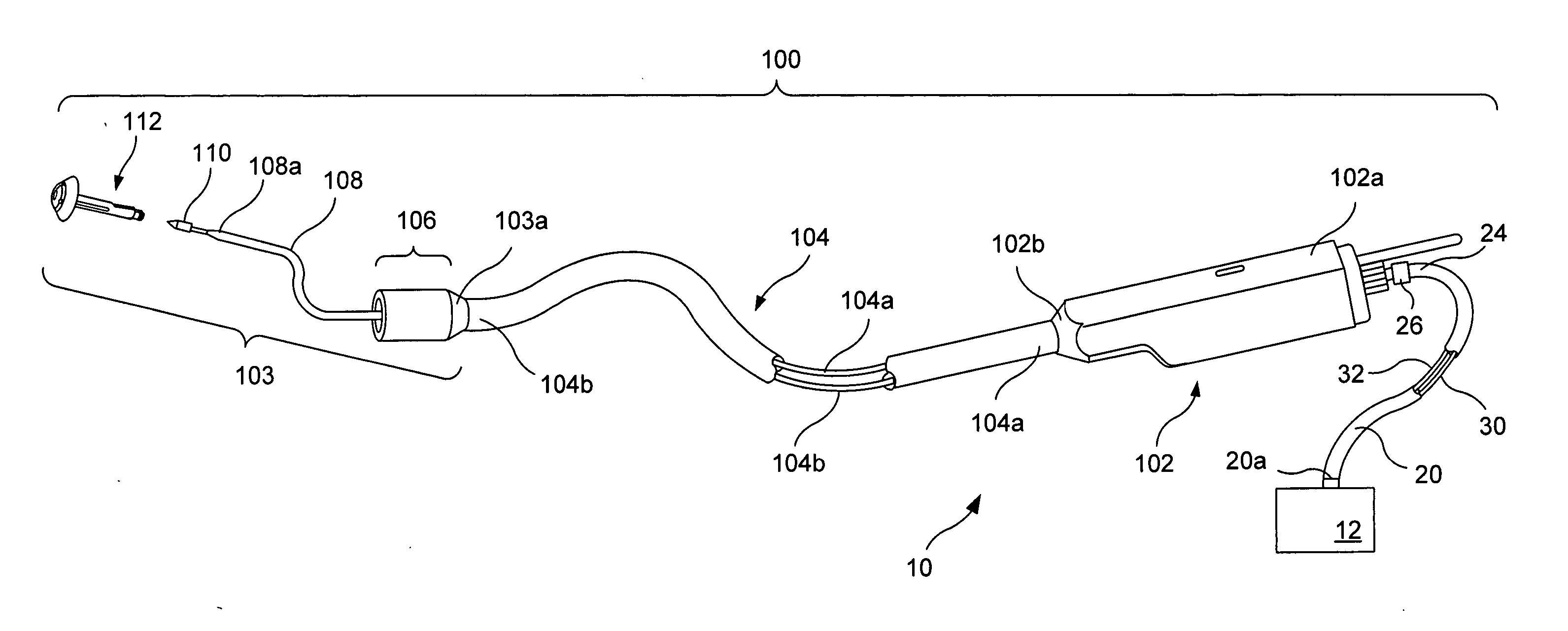
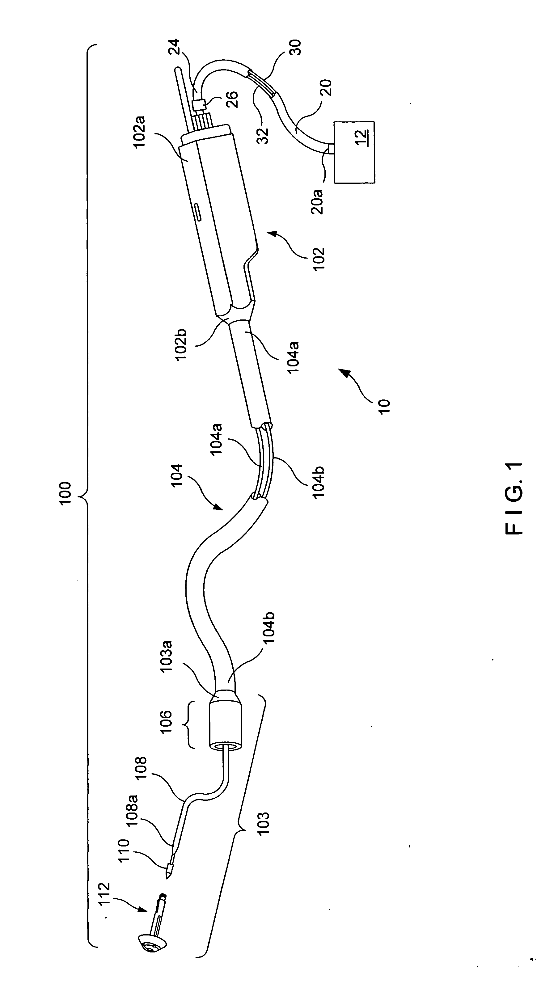
[0058] The present invention is directed to an electro-mechanical surgical system. FIG. 1 is a perspective view of an electromechanical surgical system 10 according to one embodiment of the present invention.

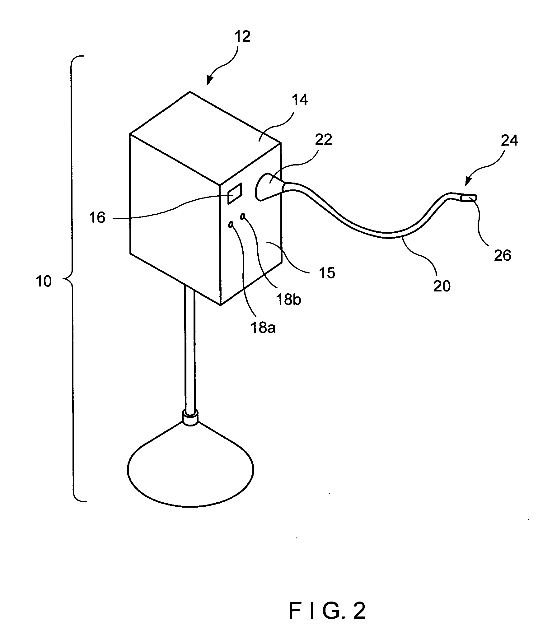
[0059] As shown in FIG. 1, the electro-mechanical surgical system 10 includes a remote power console 12 having a flexible shaft 20 extending therefrom. The flexible shaft 20 includes at least a first rotatable drive shaft 30 and a second rotatable drive shaft 32. Additional details of the remote power console 12 are described and shown in connection with, e.g., FIG. 2. Additional details of the flexible shaft 20 are described and shown in connection with, e.g., FIGS. 3 to 6.

[0060] Attached, or attachable, to a coupling 26 at the distal end 24 of the flexible cable 20 is a surgical attachment 100. The surgical attachment 100 is configured to perform a surgical operation. For the purposes of example only, the surgical attachments are described hereinbelow as being circular clamp...


PUM

PropertyMeasurementUnit
distanceaaaaaaaaaa
pressureaaaaaaaaaa
movementaaaaaaaaaa

Abstract

The present invention, in accordance with various embodiments thereof, relates to a surgical device for at least one of cutting and stapling a section of tissue. The surgical device includes a housing including at least two drivers. The surgical device also includes an anvil mechanically attachable to the housing and moveable relative to the housing between an open position and a closed position. The first driver operates to move the anvil relative to the housing to an intermediate position between the open position and the closed position. The second driver operates to move at least a portion of the housing relative to the anvil between the intermediate position and the closed position.

Description

CROSS-REFERENCE TO RELATED APPLICATIONS [0001] This application relates to U.S. patent application Ser. No. 09 / 324,452, filed on Jun. 2, 1999 and issued as U.S. Pat. No. 6,443,973, U.S. application Ser. No. 09 / 723,715, filed on Nov. 28, 2000, U.S. application Ser. No. 09 / 324,451, filed on Jun. 2, 1999 and issued as U.S. Pat. No. 6,315,184, U.S. application Ser. No. 09 / 351,534, filed on Jul. 12, 1999 and issued as U.S. Pat. No. 6,264,087, U.S. application Ser. No. 09 / 510,923, filed on Feb. 22, 2000 and issued as U.S. Pat. No. 6,517,565, U.S. application Ser. No. 09 / 510,927, filed on Feb. 22, 2000, U.S. application Ser. No. 09 / 510,932, filed on Feb. 22, 2000 and issued as U.S. Pat. No. 6,491,201, U.S. application Ser. No. 09 / 836,781, filed on Apr. 17, 2001, U.S. patent application Ser. No. 09 / 887,789, filed on Jul. 22, 2001, each of which is expressly incorporated herein in its entirety by reference.FIELD OF THE INVENTION [0002] The present invention relates to an electromechanical su...

Claims


Application Information

Patent Timeline
Patent Type & Authority Applications(United States)
IPC IPC(8): A61B17/04A61B17/115A61B17/32
CPCA61B17/115A61B2017/320052A61B17/32053A61B17/1155A61B34/74A61B34/71A61B2017/00199A61B2017/00017A61B17/068A61B2017/07285
Inventor WHITMAN, MICHAEL P.NICHOLAS, DAVID A.
Owner TYCO HEALTHCARE GRP LP
Learn More