
Driver health and fatigue monitoring system and method

a monitoring system and driver technology, applied in the direction of diagnostic recording/measuring, process and machine control, instruments, etc., can solve the problems of excessive daytime sleepiness, inattention of drivers, increased risk of motor vehicle collision,

Active Publication Date: 2014-05-13
AMERICAN VEHICULAR SCI
View PDF52 Cites 374 Cited by
  • Summary
  • Abstract
  • Description
  • Claims
  • Application Information

AI Technical Summary

Benefits of technology

This patent describes a system for monitoring a person in a vehicle, specifically the driver, by using multiple antennas placed on the seat. The antennas are selected and combined to create a strong electric field to detect changes in the person's heart rate and respiration rate, which can indicate drowsiness or sleepiness. The system can also monitor these changes over time to alert the driver if they become too abnormal, potentially preventing accidents. The technology has been tested and found to be effective and reliable.

Problems solved by technology

Driver inattention is a larger problem than driving sleepiness and fatigue.
In the medical area, drivers suffering from obstructive sleep apnea syndrome (OSAS) have an increased risk for being involved in motor-vehicle collisions.
OSA has many negative effects, including excessive daytime sleepiness, increased risk of motor vehicle accidents, hypertension, psychological distress, and cognitive impairment.
A large number of patents and technical papers address systems for detection of a drowsy driver but despite the potential for such systems, researchers have been largely unsuccessful in finding a feasible way to identify sleepiness or inattention.
However, attaching electrodes to a driver is intrusive and is not a practical solution to drowsiness detection.
Unfortunately, none of these systems have demonstrated a forecasting success rate that permits action to be taken in time for the driver to get to a location where he / she can exit the road in time.
Unfortunately, a 10-second warning is insufficient for the driver to find an exit and pull off of the road even if he / she accepts the warning of the vehicle system.
However, measuring eye closures is hampered by a driver wearing glasses, hats or other apparatus which shades the eyes from the camera, intensity of ambient light (e.g., sunlight) and in variation in the eye shape from person to person.
Thus, although there have been numerous studies and many systems developed, none has been deployed due to these and other factors.
It was then found that this method might not be the best method of monitoring the eyes for two reasons.
These approaches have a fundamental problem, however, in that the changes being measured are likely to be occurring late in the process of fatigue.
It is possible that the driver has been through a significant period of high crash risk due to lowered alertness before significant eye closure effects are able to be detected.
Other problems associated with the eye- and face-change detection technologies, are deciding on the point at which the driver is in an unsafe state and when a warning should be applied, and deciding on the nature of the warning signal itself.” (Williamson, A., Chamberlain, T.
U.S. Pat. No. 6,822,573 discloses use of a geophone in the seat and also steering wheel-based sensors for heartbeat measurement, but does not disclose how to analyze this information to obtain a measure of drowsiness.
This condition is generally not reliably achieved in practice due to the many forms of driver steering wheel interaction, especially when drowsiness in occurring.
Such a system, for example, will not work if the driver is wearing thick gloves.
The authors concluded that voluntary breaks were ineffective in substantially counteracting the effects of fatigue associated with prolonged night-time driving.
A problem with this technique is that it will eventually become tiresome and annoying to the driver.

Method used


Image

  • Driver health and fatigue monitoring system and method
  • Driver health and fatigue monitoring system and method
  • Driver health and fatigue monitoring system and method

Examples


Embodiment Construction

[0079]All patents or literature referred to anywhere in this specification are incorporated by reference in their entirety. Also, although many of the examples below relate to a particular vehicle, an automobile, the invention is not limited to any particular vehicle and is thus applicable to all relevant vehicles including all compartments of a vehicle including, for example, the passenger or other compartment of an automobile, truck, farm tractor, construction machine, train, airplane and boat.

[0080]“Or” and “and” as used in the specification and claims shall be read in the conjunctive and in the disjunctive wherever they appear as necessary to make the text inclusive rather than exclusive, and neither of these words shall be interpreted to limit the scope of the text.

[0081]There is a continuing need to recognize when a driver or machine operator is distracted in order to regain his attention before an accident results from such distraction. Distraction can take many forms as desc...


PUM


Abstract

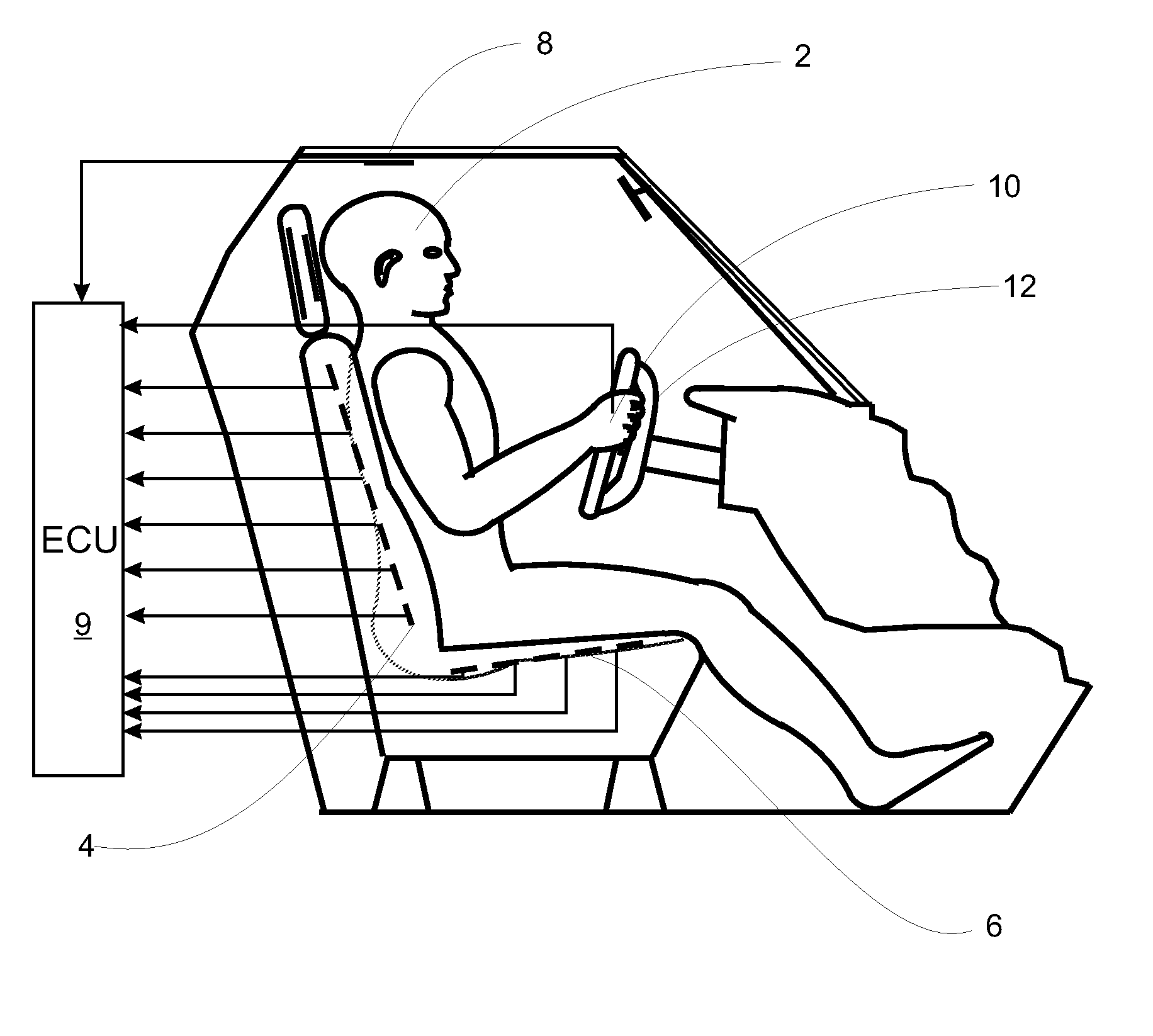
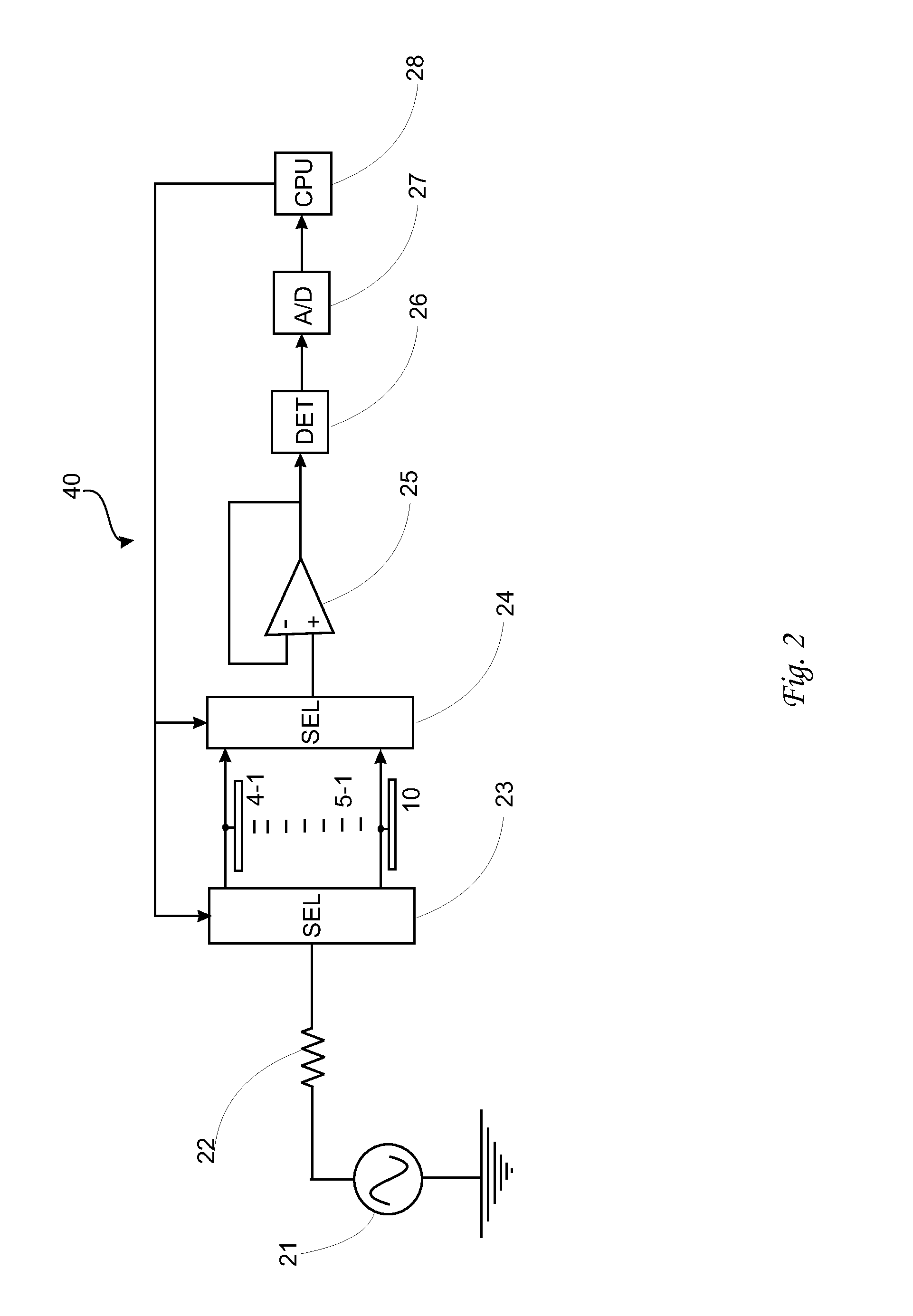
Vehicle including a seat in which an occupant sits during use of the vehicle and a monitoring system for monitoring the occupant in the seat. The monitoring system includes sets of electric field antennas, each including at least one antenna, a control unit connected to the antenna sets and including selectors coupled to the antennas. The selectors are controlled by the control unit to obtain signals from one or more antennas serving as receiving antennas and one or more antennas serving as sending antennas. The control unit determines which combination of sending antenna(s) and receiving antenna(s) provides a strongest signal in an expected heartbeat range and / or expected respiration range of the occupant and then monitors this combination for changes and / or deviations from a normal range of heartbeats and / or respiration.

Description

CROSS REFERENCE TO RELATED APPLICATIONS[0001]This application claims priority under 35 U.S.C. §119(e) of U.S. provisional patent application Ser. Nos. 61 / 452,469 filed Mar. 14, 2011 and 61 / 547,798 filed Oct. 17, 2011, both of which are incorporated by reference herein.FIELD OF THE INVENTION[0002]The present invention relates generally to systems and methods for monitoring a driver of a vehicle to determine at least one characteristic, condition, property and / or state of the driver, for example, whether the driver is falling asleep or otherwise unable to operate the vehicle.BACKGROUND OF THE INVENTION[0003]There are several different vehicular situations that are lumped together and called the distracted or inattentive driver problem. These situations include cases where the driver is wide-awake but eating, putting on make-up, texting and talking on the phone; cases where the driver is physically fatigued and may or may not also be sleepy; medical condition cases where the driver suf...

Claims


Application Information

Patent Timeline
IPC IPC(8): G05D1/00
CPCG08B21/06A61B5/7221A61B5/02405A61B5/11A61B5/18A61B5/6892A61B5/0507A61B5/746A61B5/6893G05D1/00A61B5/0077A61B5/163
Inventor BREED, DAVID, S
Owner AMERICAN VEHICULAR SCI
Learn More