Radiating fan and base of fan frame

A cooling fan and frame technology, which is applied to instruments, electrical digital data processing, digital data processing components, etc., can solve problems such as loss of electronic components and shortening of life.

Inactive Publication Date: 2006-03-15
DELTA ELECTRONICS INC
View PDF0 Cites 15 Cited by
  • Summary
  • Abstract
  • Description
  • Claims
  • Application Information

AI Technical Summary

Problems solved by technology

[0002] In general electronic products (such as computers), since the electronic components in them will generate a lot of heat duri

Method used


Image

  • Radiating fan and base of fan frame
  • Radiating fan and base of fan frame
  • Radiating fan and base of fan frame

Examples


Embodiment Construction

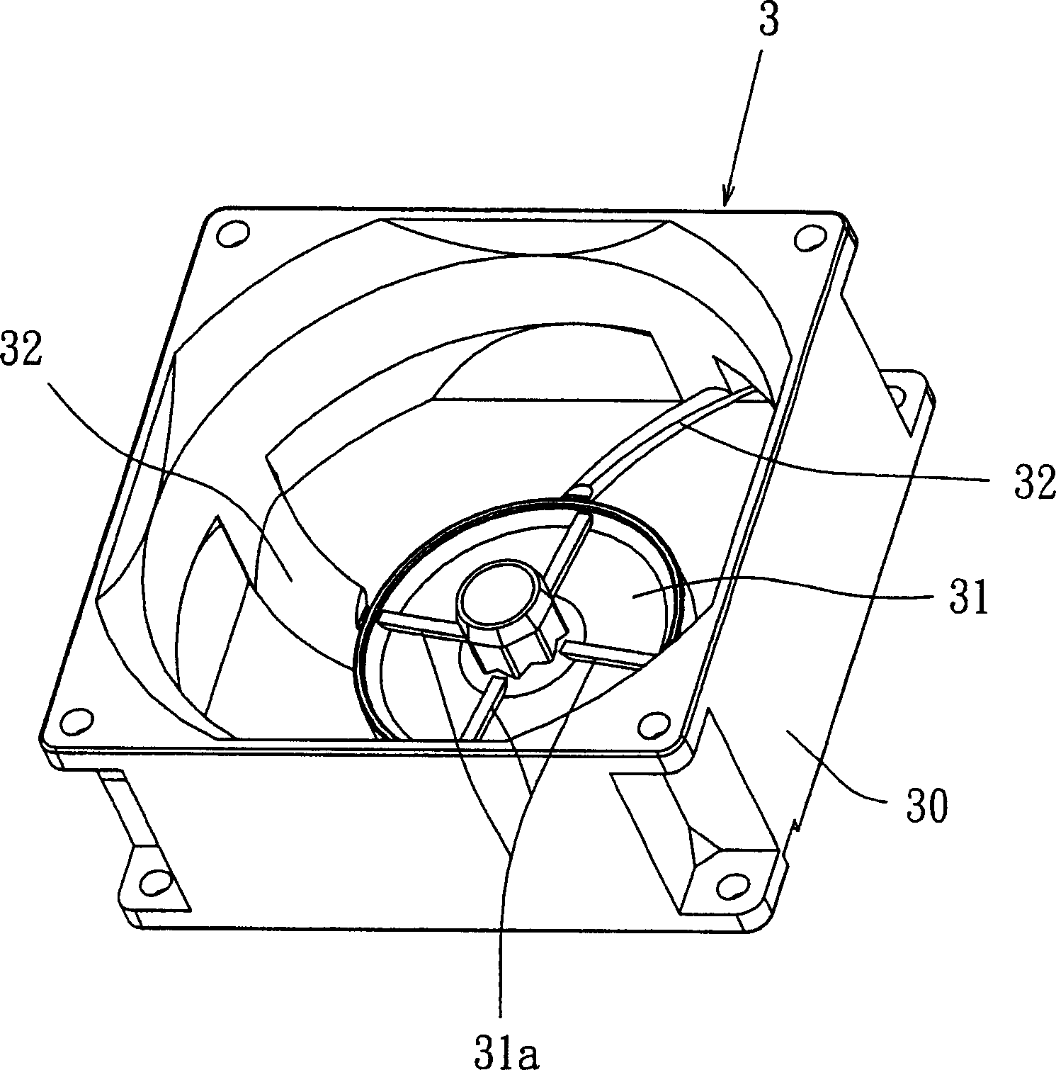
[0053] First, see image 3 , which shows a preferred embodiment of one of the fan frame seats used in the cooling fan of the present invention. The fan frame seat 3 includes an outer frame 30; a base 31, which is arranged in the outer frame, for supporting the impeller of the cooling fan; and a plurality of deflectors 32, which are arranged on the base 31 Between the outer frame 30, the plurality of deflectors are located on the side of the air outlet of the fan frame seat. Certainly, the deflector can also be arranged on the air inlet side of the fan frame seat, or be located on the air inlet side and the air outlet side of the fan frame seat at the same time. The shape of the frame is in addition to the image 3 Instead of being shown as a square configuration, it could also be a rectangular or circular configuration. The outer frame, the base and the plurality of deflectors can be integrally formed by injection molding, and the materials used can be plastic, metal or oth...


PUM


Abstract

This invention is a heat emission fan and its frame base. The fan comprises a frame, an impeller formed by a wheel hub and motive blades around the hub. The frame base is installed inside the fan frame to support the impeller. Several flow guiders are fixed in between the frame base and the frame. The flow guiders have the first and the second curve surfaces to largely decrease noise and increase wind pressure.

Description

technical field [0001] The invention relates to a cooling fan and its fan frame seat, in particular to a fan frame seat applied to an axial flow fan. Background technique [0002] In general electronic products (such as computers), since the electronic components in them generate a lot of heat during operation, if they are kept at high temperature, it will easily lead to wear and tear of electronic components and shorten their lifespan. Therefore, in order to prevent electronic components from malfunctioning, cooling fans are generally provided therein to dissipate the heat generated inside to the outside. [0003] see figure 1 , which is a traditional commonly used axial flow fan, the axial flow fan has a housing 90, a stator 91 and an impeller 93. The casing 90 can be combined with the stator 91 , and the shaft 94 of the impeller 93 is inserted into the shaft hole of the stator 91 and supported by the bearing 92 . When the impeller 93 rotates, the blades 95 on it drive ...

Claims


Application Information

Patent Timeline
IPC IPC(8): F04D29/66F04D29/54F04D29/38F04D29/02G06F1/20
Inventor 颜承伟林祖亮黄文喜
Owner DELTA ELECTRONICS INC
Why Eureka
Try Eureka