
Exhaust assembly for dish-washing machine and dish-washing machine

A technology for dishwashers and components, which is applied in the washing machine/rinsing machine of tableware, parts and applications of washing machine/rinsing washing machine of tableware, etc. It can solve the problem of small noise reduction frequency range, single water vapor discharge, and noise reduction effect Attenuation and other issues, to achieve the effect of large noise reduction frequency range

Inactive Publication Date: 2021-01-19
GUANGDONG MIDEA WHITE HOME APPLIANCE TECH INNOVATION CENT CO LTD +1
View PDF5 Cites 0 Cited by
  • Summary
  • Abstract
  • Description
  • Claims
  • Application Information

AI Technical Summary

Problems solved by technology

[0002] The exhaust channel of the dishwasher is a part of the drying system of the dishwasher. The water vapor generated during the process of drying the dishes in the dishwasher is discharged out of the dishwasher through the exhaust channel, but due to its non-tightness, During the entire operation of the dishwasher, the exhaust channel of the dishwasher is also one of the paths for the noise to come out. At present, the structural design of the exhaust channel of the dishwasher mainly considers the single structural function of discharging water vapor, and most of them do not take into account As the path of noise transmission, noise reduction and noise reduction are required
[0003] The means for the dishwasher in the prior art to reduce the noise of the exhaust passage is mainly to set corresponding structures in the exhaust passage to reflect and block the sound, or to wrap sound-absorbing and sound-insulating materials for sound noise reduction. However, the noise reduction effect of this processing method is not ideal, the noise reduction frequency range is small, and with the aging of sound absorption and sound insulation materials, the noise reduction effect will also be significantly weakened

Method used


Image

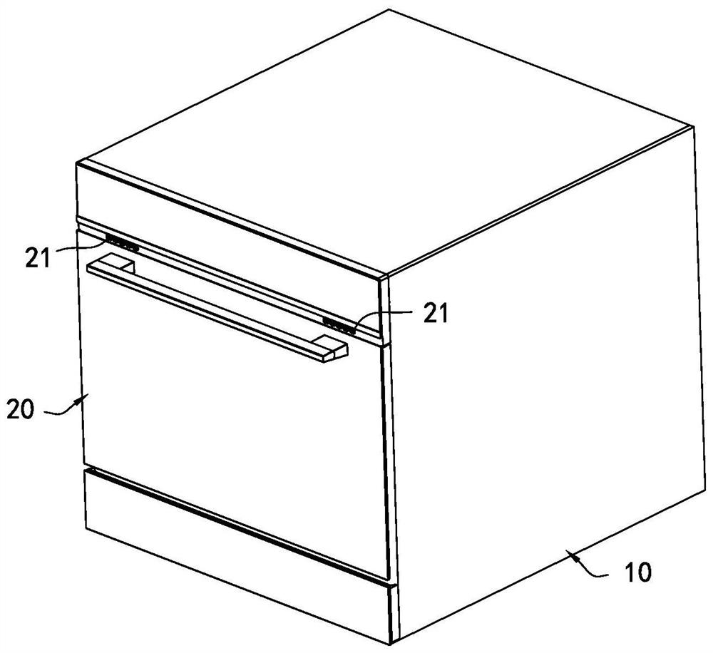
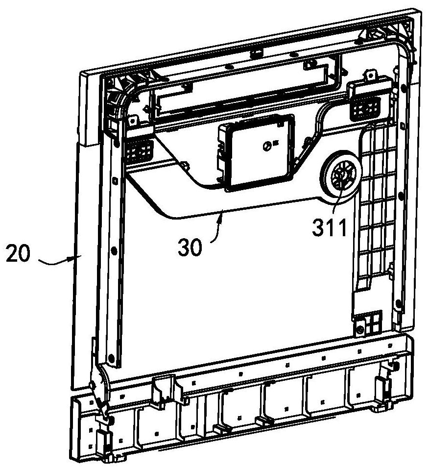
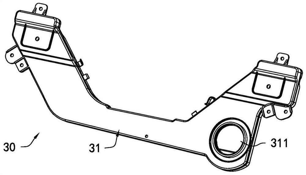
  • Exhaust assembly for dish-washing machine and dish-washing machine
  • Exhaust assembly for dish-washing machine and dish-washing machine
  • Exhaust assembly for dish-washing machine and dish-washing machine

Examples


Embodiment Construction

[0029] This part will describe the specific embodiment of the present invention in detail, and the preferred embodiment of the present invention is shown in the accompanying drawings. Each technical feature and overall technical solution of the invention, but it should not be understood as a limitation on the protection scope of the present invention.

[0030] In the description of the present invention, it should be understood that the orientation descriptions, such as up, down, front, back, left, right, etc. indicated orientations or positional relationships are based on the orientations or positional relationships shown in the drawings, and are only In order to facilitate the description of the present invention and simplify the description, it does not indicate or imply that the device or element referred to must have a specific orientation, be constructed and operated in a specific orientation, and thus should not be construed as limiting the present invention.

[0031] I...


PUM


Abstract

The invention discloses an exhaust assembly for a dish-washing machine and the dish-washing machine. The exhaust assembly comprises a shell wherein an exhaust channel is formed in the shell, and the exhaust channel is provided with an air inlet and an air outlet; at least two partition plates which are arranged in the exhaust channel in the exhaust direction to form at least one silencing cavity,wherein airflow through holes matched with the silencing cavities to form through-flow section mutation are formed in the partition plates, and the through-flow section in the exhaust channel is mutated, so that sound waves with specific frequency are reflected and interfered at the through-flow section mutation position, and further, the airflow noise is effectively reduced. The number, the volume, the positions and the like of the silencing cavities are reasonably selected according to the specific noise frequency, and the exhaust channel is constructed to reduce noise of the specific frequency band, so that the exhaust channel has a large noise reduction frequency band range.

Description

technical field [0001] The invention relates to the technical field of washing appliances, in particular to an exhaust assembly for a dishwasher and the dishwasher. Background technique [0002] The exhaust channel of the dishwasher is a part of the drying system of the dishwasher. The water vapor generated during the process of drying the dishes in the dishwasher is discharged out of the dishwasher through the exhaust channel, but due to its non-tightness, During the entire operation of the dishwasher, the exhaust channel of the dishwasher is also one of the paths for the noise to come out. At present, the structural design of the exhaust channel of the dishwasher mainly considers the single structural function of discharging water vapor, and most of them do not take into account As a path for noise transmission, noise reduction and noise reduction are required. [0003] The means for the dishwasher in the prior art to reduce the noise of the exhaust passage is mainly to s...

Claims


Application Information

Patent Timeline
IPC IPC(8): A47L15/48A47L15/42A47L15/00
CPCA47L15/488A47L15/4257A47L15/00
Inventor 刘剑博张良程繁华李忠华李翔
Owner GUANGDONG MIDEA WHITE HOME APPLIANCE TECH INNOVATION CENT CO LTD
Learn More