Driving circuit and driving method for an electrophoretic display

A technology of electrophoretic display and driving circuit, which can be applied to static indicators, instruments, etc., and can solve problems such as appearance dependence

Inactive Publication Date: 2006-07-05
KONINKLIJKE PHILIPS ELECTRONICS NV
View PDF4 Cites 9 Cited by
  • Summary
  • Abstract
  • Description
  • Claims
  • Application Information

AI Technical Summary

Problems solved by technology

[0006] Known display devices have the disadvantage that the appearance of a pixel depends on the history of the voltage supplied across the pixel

Method used


Image

  • Driving circuit and driving method for an electrophoretic display
  • Driving circuit and driving method for an electrophoretic display
  • Driving circuit and driving method for an electrophoretic display

Examples


Embodiment Construction

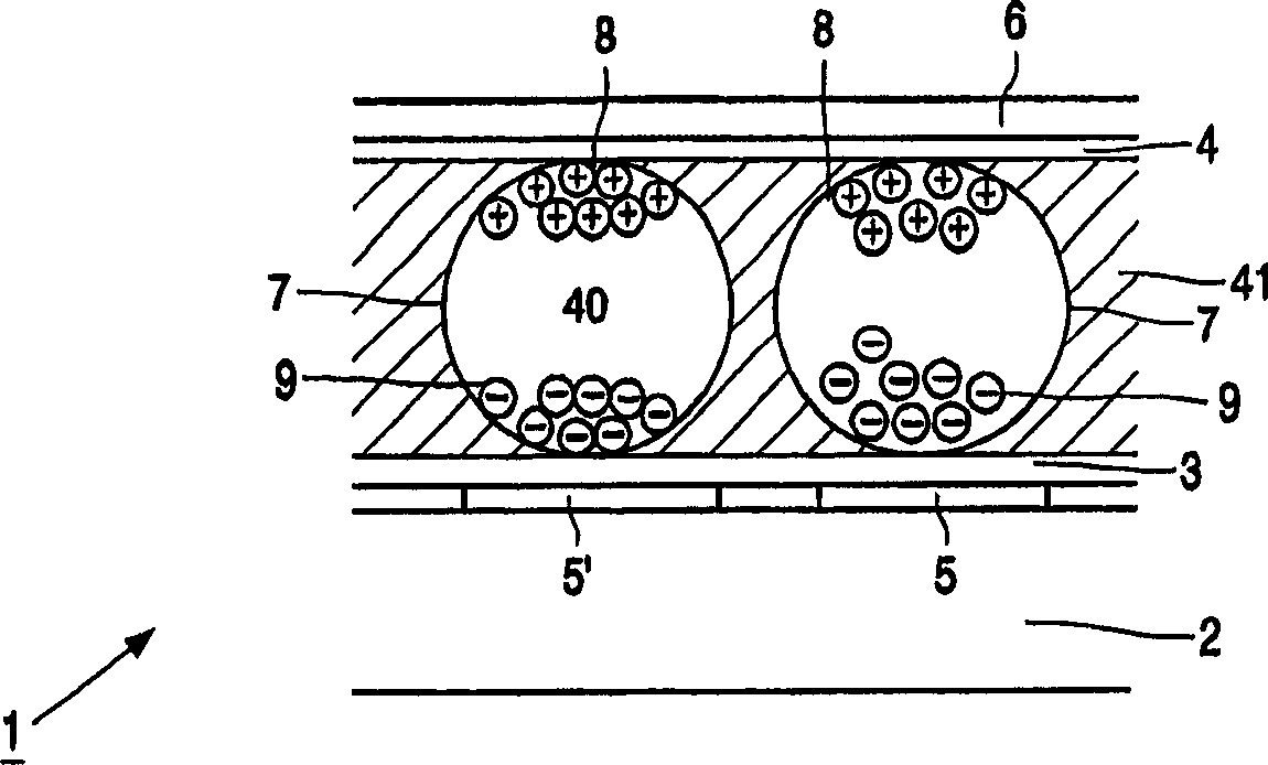
[0032] figure 1Diagrammatically shows a cross-section of a part of an electrophoretic display, for example the size of only a few display elements, comprising a base substrate 2, an electrophoretic film with electronic ink present on two transparent substrates 3 and 4, for example made of polyethylene between. One of the substrates 3 is provided with transparent pixel electrodes 5 , 5 ′, and the other substrate 4 is provided with a transparent counter electrode 6 . The electronic ink includes a plurality of microcapsules 7 of about 10 to 50 microns. Each microcapsule 7 comprises positively charged white particles 8 and negatively charged black particles 9 suspended in a fluid 40 . The hatched material 41 is a polymeric binder. Layer 3 is not required, or may be an adhesive layer. When the pixel voltage VD (see FIG. 2 ) across the pixel 18 is supplied as a positive drive voltage Vdr (see eg FIG. 3 ) to the pixel electrode 5 , 5 ′ opposite the counter electrode 6 , a movemen...


PUM


Abstract

A driving circuit for an electrophoretic display has a plurality of pixels (18) of an electrophoretic material which comprises charged particles (8, 9). The pixels (18) are associated with a respective first electrode (6) and second electrode (5, 5') which present a drive voltage (VD) to the pixels (18) to at least enable the charged particles (8, 9) to occupy one of two limit positions between the first electrode (6) and the second electrode (5, 5'). The driving circuit comprises an addressing circuit (16, 10) which generates the drive voltage (VD) by applying between the first electrode (6) and the second electrode (5, 5'): (i) an reset pulse (RE) which has an energy content sufficient or larger than required for the charged particles (8, 9) to reach one of the limit positions, and (ii) a shaking pulse (SP1) which at least partially overlaps the reset pulse (RE). The shaking pulse SP1 has, during the reset pulse (RE), at least partially a level with an opposite polarity than a level of the reset pulse (RE). The shaking pulse (SP1) comprises at least one preset pulse (PR) having an energy sufficient to release the charged particles (8, 9) present in one of the limit positions, but insufficient to enable said particles (8, 9) to reach the other one of the limit positions.

Description

technical field [0001] The present invention relates to an electrophoretic display, a driving circuit for such an electrophoretic display, a display device comprising such an electrophoretic display, and a method of driving such an electrophoretic display. Background technique [0002] A display device of the type mentioned in the opening paragraph is known from International Patent Application WO 99 / 53373. This patent application discloses an electronic ink display (also known as an E-ink display) comprising two substrates, one of which is transparent and the other substrate is provided with electrodes arranged in rows and columns. Display elements, or pixels, are associated with the intersections of row and column electrodes. Each display element is coupled to a column electrode via a main electrode of a thin film transistor (also referred to as TFT). The gates of the TFTs are coupled to the row electrodes. This arrangement of display elements, TFTs and row and column e...

Claims


Application Information

Patent Timeline
Patent Type & Authority Applications(China)
IPC IPC(8): G09G3/34
CPCG09G2310/065G09G2310/061G09G2310/0205G09G2300/08G09G2310/068G09G3/344
Inventor G·周P·A·杜恩伊M·T·约翰逊N·艾勒内
Owner KONINKLIJKE PHILIPS ELECTRONICS NV
Why Eureka
Try Eureka