Rolling-mill housing for rolling bar-type or tube-type rolling piece

A technology of rolling mill stand and tube shape, applied in the direction of metal rolling stand, metal rolling mill stand, metal rolling, etc., can solve the problems such as the change of side clearance, and achieve the effect of simple moving performance

Inactive Publication Date: 2010-05-05
KOCKS TECH GMBH & CO
View PDF3 Cites 0 Cited by
  • Summary
  • Abstract
  • Description
  • Claims
  • Application Information

AI Technical Summary

Problems solved by technology

[0004] If the shafts, viewed from the midpoint of the hole opening, move in unison with each other, radially outwards and each parallel to the axis, then the problem arises that when the bevel gears are fixed axially on the shafts that support them respectively When on the shaft, the side clearance (backlash) of the bevel gear transmission formed by the bevel gears meshing with each other is changed

Method used


Image

  • Rolling-mill housing for rolling bar-type or tube-type rolling piece
  • Rolling-mill housing for rolling bar-type or tube-type rolling piece

Examples


Embodiment Construction

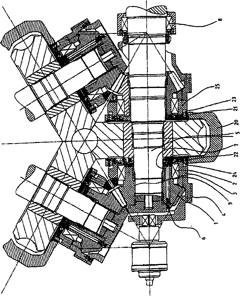
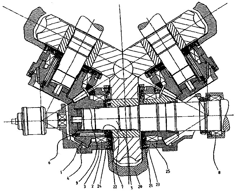
[0016] As can be seen from the drawing, the bevel gear 1 , supported on the eccentric sleeve 3 via rolling bearings 2 , passes through each of the trapezoids arranged on the outside on the eccentric sleeve 3 in a known manner when the eccentric sleeve 3 rotates. Thread 4 moves along the axial direction. The bevel gear thus moves axially on the roller shaft 5 , which is radially supported in the bevel gear via bushings 6 , 7 , but is fixed in its axial position by an axial bearing 8 . The torque is positively transmitted by the roller shaft 5 via the involute mesh 9 to the bevel gear.

[0017] The clip 20 engages via projections 21 , 22 in axially formed grooves 23 , 24 of the eccentric sleeves 3 , 25 . Thus, the rotational movements of these eccentric sleeves are synchronized. However, the eccentric sleeves can be moved axially away from or closer to each other.

[0018] Through this structure, the shaft can be moved precisely and parallel to the axial direction.


PUM


Abstract

A rolling-mill frame for rolling rod-shaped or tube-shaped rolled pieces comprises at least one shaft arranged in a housing for supporting a roller, and sleeves arranged on the shaft on both sides ofthe roller along the axial direction and supported in a radial bearing, wherein the radial bearing is supported in bearing liners rotatablely arranged in the housing. The rolling-mill frame also includes a connector for transmitting the rotation movement of one bearing liner to another with respect to the housing, wherein at least one bearing liner is movably arranged along the shaft with respectto the connector.

Description

technical field [0001] The invention relates to a rolling stand for rolling rod-shaped or tubular rolled products, such as wire or tubular products. Background technique [0002] Rod-shaped or tubular rolled products are rolled in a rolling mill through a rolling stand, wherein a plurality of rollers arranged in a plane and forming a central pass opening are arranged in the rolling stand. Typically, three or four rollers are arranged such that they form a central pass opening between them. Constructions of such rolling stands are known which have only one rotary drive. A bevel gear arranged on a shaft that meshes with a bevel gear arranged on an adjacent shaft transmits the torque of the driving shaft to the shaft supporting the other rollers. For example, EP1449597A2 discloses one such rolling mill stand structure. [0003] As disclosed in EP1449597A2, such rolling stands generally have the possibility of adjusting the pass opening. The pass openings are made larger or ...

Claims


Application Information

Patent Timeline
IPC IPC(8): B21B31/02B21B31/26B21B13/10
CPCB21B13/103B21B31/26
Inventor H·波特霍夫
Owner KOCKS TECH GMBH & CO
Why Eureka
Try Eureka