Heat sink apparatus for electronic device

A technology for electronic devices and heat sinks, which is applied in heat exchange equipment, lighting and heating equipment, and structural components of electrical equipment, etc. It can solve the problems of increasing the thickness of heat sinks and the inability to use microchannel heat sink components

Inactive Publication Date: 2006-10-18
SAMSUNG ELECTRONICS CO LTD
View PDF3 Cites 23 Cited by
  • Summary
  • Abstract
  • Description
  • Claims
  • Application Information

AI Technical Summary

Problems solved by technology

[0011] However, the microchannel layer and the manifold layer are directly connected to each other, which increases the thickness of the heat sink
Therefore, microchannel heat sink assemblies cannot be used in slim electronic devices

Method used


Image

  • Heat sink apparatus for electronic device
  • Heat sink apparatus for electronic device
  • Heat sink apparatus for electronic device

Examples


Embodiment Construction

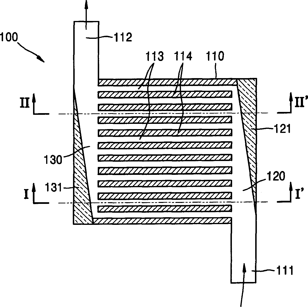
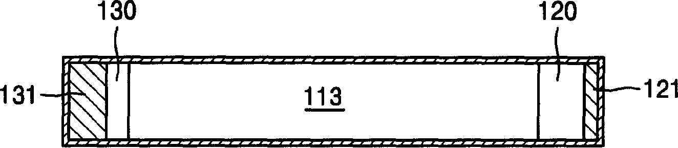
[0029] figure 2 is a front view of a cross section of a heat sink apparatus 100 for an electronic device (not shown) according to a first exemplary embodiment of the present invention. image 3 is along figure 2 The front view of the cross-section of the heat sink device 100 cut by the line I-I' in . Figure 4 is along figure 2 The front view of the cross-section of the heat sink device 100 cut by the line II-II' in .

[0030] refer to figure 2 , the radiator device 100 includes a main body 110 , a plurality of channels 113 , an inflow guide unit 120 and an outflow guide unit 130 .

[0031] The sucked fluid enters the body 110 and absorbs heat generated by the electronic device. The main body 110 is sealed except for an inlet 111 and an outlet 112 through which the heat absorbing fluid flows.

[0032] The plurality of passages 113 are partitioned at predetermined intervals by the plurality of passage walls 114 inside the main body 110 so that heat absorbing fluid can...


PUM


Abstract

The present invention provides a heat sink device for an electronic device. The heat sink device includes a body having an inlet and an outlet formed therein. The heat absorbing fluid flows through a plurality of channels. As the inflow guiding unit extends away from the inlet, the cross section of the inflow guiding unit narrows for guiding substantially the same amount of heat absorbing fluid into each of the channels. An outflow guide unit is formed substantially identically to the inflow guide unit for guiding the heat absorbing fluid from the channel to the outlet.

Description

[0001] This application claims the benefit of Korean Patent No. 10-2005-0029954 filed with the Korean Intellectual Property Office on Apr. 11, 2005, the entire contents of which are hereby incorporated by reference. technical field [0002] The present invention relates to a heat sink device for an electronic device. More particularly, the present invention relates to a heat sink apparatus for an electronic device that maintains a uniform flow of heat absorbing fluid so that the temperature of the surface contacting the electronic device is substantially uniform. Background technique [0003] Typically, amplifiers of communication repeaters or electronics of audio equipment, or computer electronics such as central processing units (CPUs), graphics cards, power supplies, and other similar electronics, generate heat while operating. [0004] Since electronic devices are affected by their surrounding environment, these electro...

Claims


Application Information

Patent Timeline
Patent Type & Authority Applications(China)
IPC IPC(8): H05K7/20G06F1/16G12B15/02H01L23/473
CPCH05K7/20254F28F9/0263H05K7/20
Inventor 朴熙成金光姜钟泰
Owner SAMSUNG ELECTRONICS CO LTD
Why Eureka
Try Eureka