Backrest reclining apparatus

A technology of tilting device and backrest, which is applied in the direction of movable seats, transportation and packaging, special positions of vehicles, etc.

Inactive Publication Date: 2006-11-15
KOKUYO CO LTD
View PDF2 Cites 5 Cited by
  • Summary
  • Abstract
  • Description
  • Claims
  • Application Information

AI Technical Summary

Problems solved by technology

In addition, the purpose of the present invention is to provide such a backrest tilting device: it can easily meet the requirement of setting a large backrest tilting range, and realize a

Method used


Image

  • Backrest reclining apparatus
  • Backrest reclining apparatus
  • Backrest reclining apparatus

Examples


Embodiment Construction

[0042] The constitution of the present invention will be described in detail below according to the embodiments shown in the drawings.

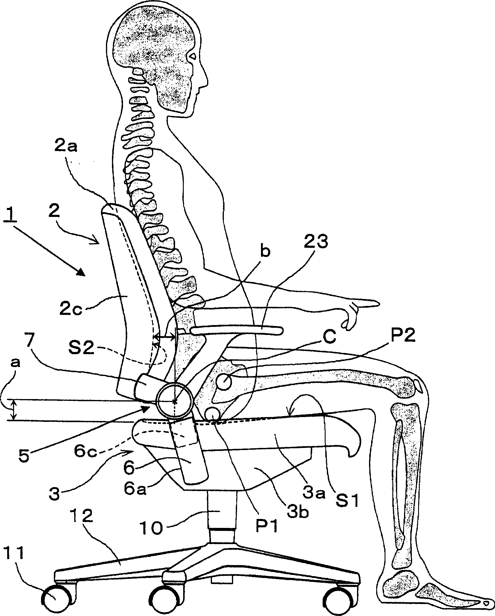
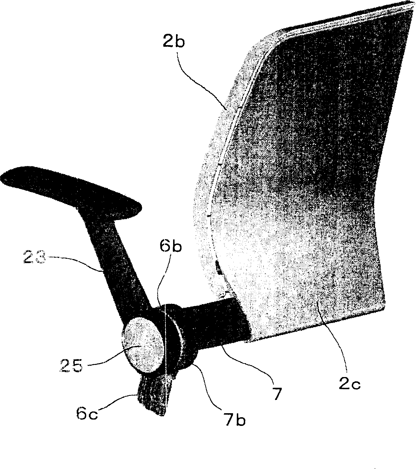
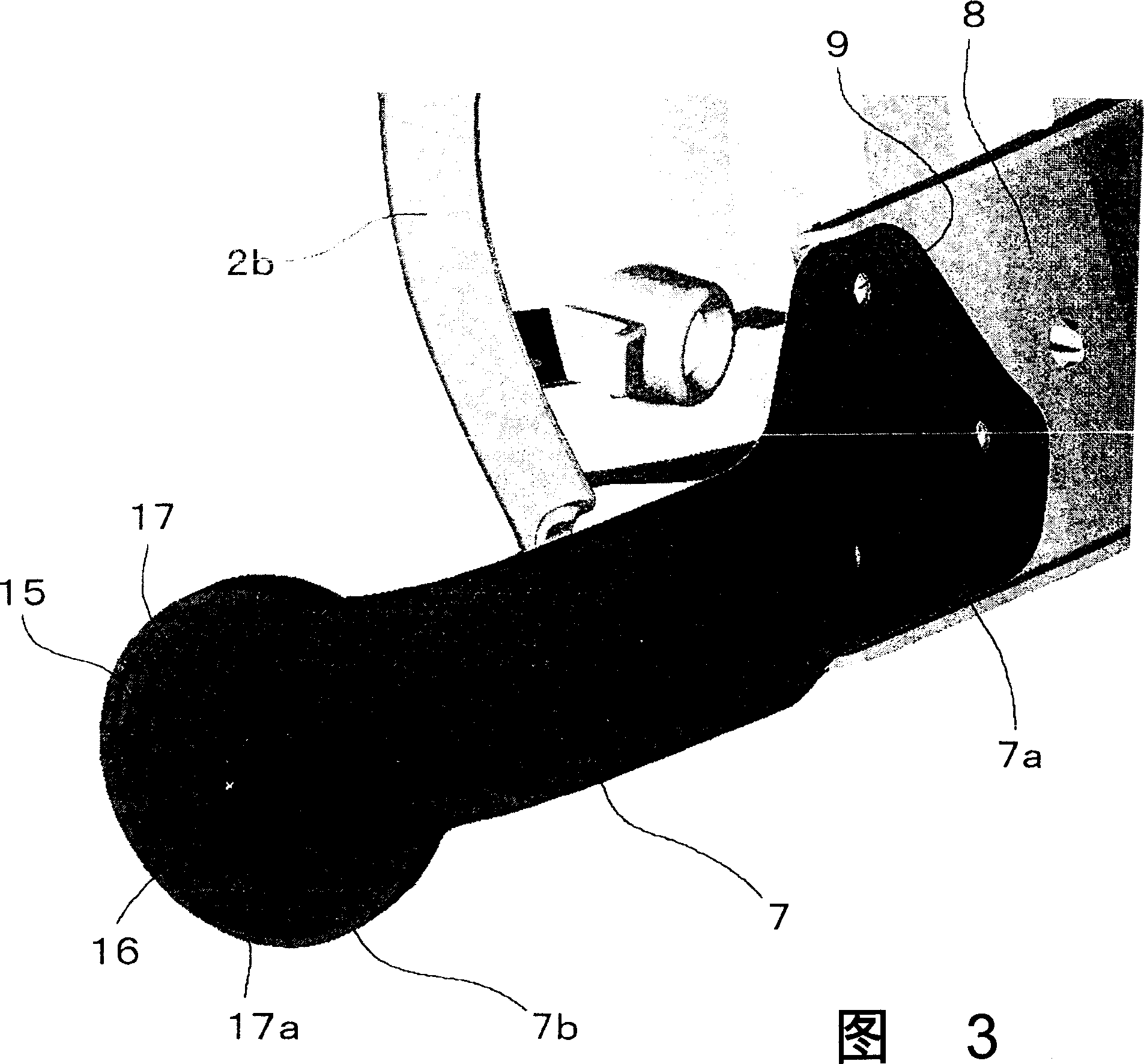
[0043] Figure 1 to Figure 6 One embodiment of the backrest tilting device of the present invention is shown. In this embodiment, the case where the backrest tilting device 5 of the present invention is applied to a swivel chair 1 for an office with a tiltable backrest will be described. On the other hand, in this specification, the term "front" refers to the front side of the seated person, and "upper" refers to the upper side in the vertical direction.

[0044] In the chair 1 having the backrest tilting device 5 capable of tiltingly connecting the backrest 2 to the seat 3, the rotation center C of the backrest 2 is set at a position corresponding to the seat surface S1 or the seat surface S1 above and in front of the frontmost point (hereinafter referred to as the backrest point) of the backrest S2 in the longitudinal center of the backre...


PUM


Abstract

A backrest reclining apparatus for tiltably connecting the backrest of a chair or a seat for a vehicle to the seat thereof. To reduce a load on the hip portion or the waist and back portions of a seated person when the backrest is tilted, the rotating center (C) of the backrest (2) is set over the bearing surface (S1) of the seat and forward of the backrest surface (S2) of the backrest and on the side closer to the bearing surface (S1) and the backrest surface (S2) than the trochanterion (P2) of the seated person seating on the seat (3).

Description

technical field [0001] The invention relates to a backrest tilting device. More specifically, the present invention relates to a structure of a backrest tilting device in which a backrest of a chair or a vehicle seat is tiltably connected to the seat. Background technique [0002] In the past, for the swing chair or vehicle seat whose backrest is tiltably connected to the seat, such as disclosed in JP-A-5-8676, JP-A-6-253943, and JP-A-6-64546 disclosed in the Japanese Patent Office. As mentioned above, there is a technique of aligning the center of rotation of the backrest with a point seen from the side of the occupant's hip joint axis called the rotor point. Figure 7 It shows the backrest 101 and the seated person before and after rotating backward about the rotor point P2, that is, tilting, according to the above-mentioned conventional technology. In this prior art, the center of rotation C of the backrest 101 coincides with or is set near the rotor point P2, which is t...

Claims


Application Information

Patent Timeline
IPC IPC(8): A47C1/024A47C3/026A47C1/035B60N2/22
CPCB60N2/2227A47C7/444
Inventor 堀木敏幸
Owner KOKUYO CO LTD
Why Eureka
Try Eureka