Clock pulse generating circuit

A technology for generating circuits and clock pulses, applied in time-division multiplexing selection devices, electrical components, generating/distributing signals, etc., can solve problems such as available frequency limitations, and achieve the effect of slowing down frequency limitations and avoiding abnormalities

Inactive Publication Date: 2010-06-02
RICOH KK
View PDF4 Cites 0 Cited by
  • Summary
  • Abstract
  • Description
  • Claims
  • Application Information

AI Technical Summary

Problems solved by technology

[0015] Furthermore, in the prior art, since the reference frequency-divided clock pulses input to the clock pulse switching circuit 125 are all converted into the same frequency, the available frequencies of the complex input reference clock pulses are limited to some extent.

Method used


Image

  • Clock pulse generating circuit
  • Clock pulse generating circuit
  • Clock pulse generating circuit

Examples


Embodiment Construction

[0041] Hereinafter, embodiments of the present invention will be described with reference to the drawings. The following description is for a better understanding of the present invention, and does not limit the scope of the present invention in any way.

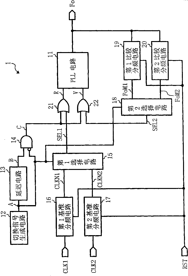
[0042] figure 1 It is a configuration diagram of the clock pulse generating circuit of the first embodiment of the present invention.

[0043] in figure 1 Here, the clock pulse generating circuit 1 switches between the input clock pulses CLK1 and CLK2, uses the selected input clock pulse as a reference clock pulse, generates and outputs an output clock pulse Fo having a predetermined frequency based on the reference clock pulse. In addition, in the first embodiment of the present invention, a case where there are two input clock pulses is described as an example, and the present invention is not limited to this. The present invention can be applied to occasions where there are plural input clock pulses. At this time, it can b...


PUM


Abstract

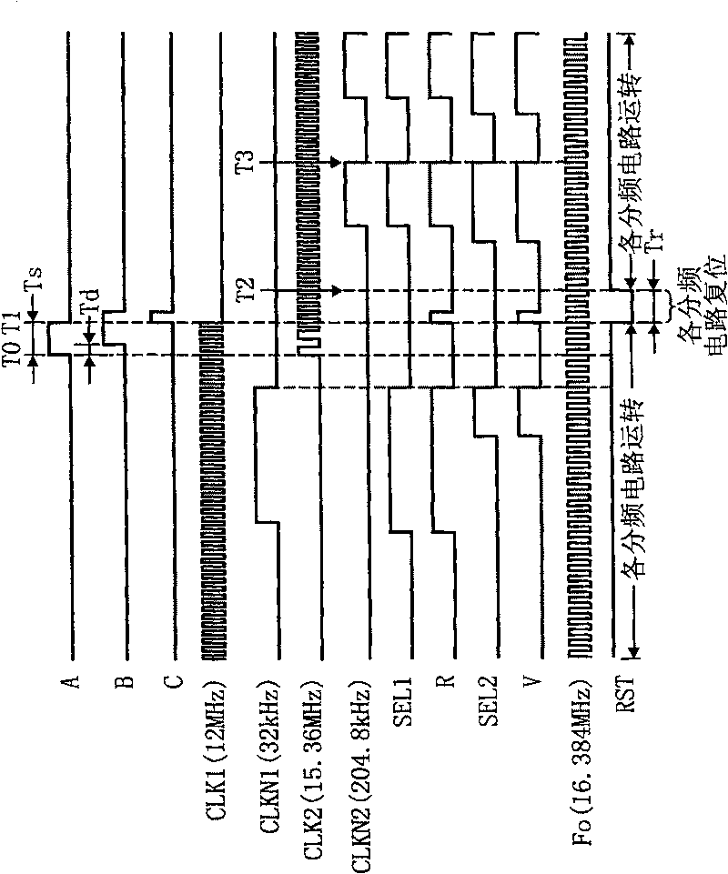
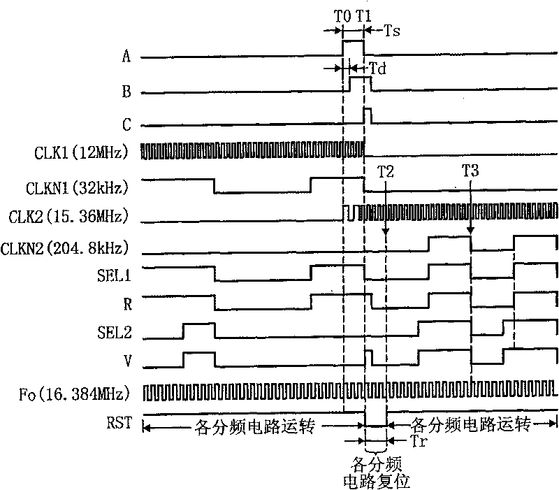
The invention is to obtain a clock generation circuit having a PLL circuit and capable of evading the generation of abnormality at the switching of clocks independently of the signal levels of a current reference frequency dividing clock and a switched reference frequency dividing clock and the signal level of a comparing frequency dividing signal at the switching of clocks, and capable of sharplyeasing limitation in frequencies to be used for an input reference clock. Immediately after switching of input clocks CLK1, CLK2, first and second reference frequency dividing circuits 16, 17 and first and second comparing frequency dividing circuits 19, 20 are respectively reset, a pulse signal C is respectively added to a reference selection clock SEL1 outputted from a first selection circuit 15 and a comparison selection clock SEL2 outputted from a second selection circuit 18 and respective clocks SEL1, SEL2 to which the pulse signal C is respectively added are inputted to the PLL circuit11.

Description

Technical field [0001] The present invention relates to a clock pulse (Clock) generating circuit with a PLL (Phase Lock Loop) circuit, in which switching selection is performed among plural input clock pulses, and the selected clock pulse is used as a reference clock pulse, and based on the reference clock pulse A clock pulse of a predetermined frequency is generated and output. Background technique [0002] Figure 4 It is a block diagram illustrating an example of the prior art (for example, Japanese Patent Laid-Open No. 7-170584). Figure 5 Yes means attached Figure 4 The timing chart of the waveform of each signal. [0003] in Figure 4 In the clock pulse generating circuit 100 shown, the first input reference clock pulse 101, the second input reference clock pulse 102, and the third input reference clock pulse 103 are respectively input to the corresponding frequency dividing circuits 121-123, and pass the frequency division The circuits 121-123 are converted into reference div...

Claims


Application Information

Patent Timeline
Patent Type & Authority Patents(China)
IPC IPC(8): H04Q11/04H03L7/08G06F1/04H04L7/00
Inventor 杉浦义信松岛诚
Owner RICOH KK
Why Eureka
Try Eureka