

Clock pulse generating circuit
A technology for generating circuits and clock pulses, applied in time-division multiplexing selection devices, electrical components, generating/distributing signals, etc., can solve problems such as available frequency limitations, and achieve the effect of slowing down frequency limitations and avoiding abnormalities
- Summary
- Abstract
- Description
- Claims
- Application Information
AI Technical Summary
Problems solved by technology
Method used
Image

Examples
Embodiment Construction
[0041] Hereinafter, embodiments of the present invention will be described with reference to the drawings. The following description is for a better understanding of the present invention, and does not limit the scope of the present invention in any way.
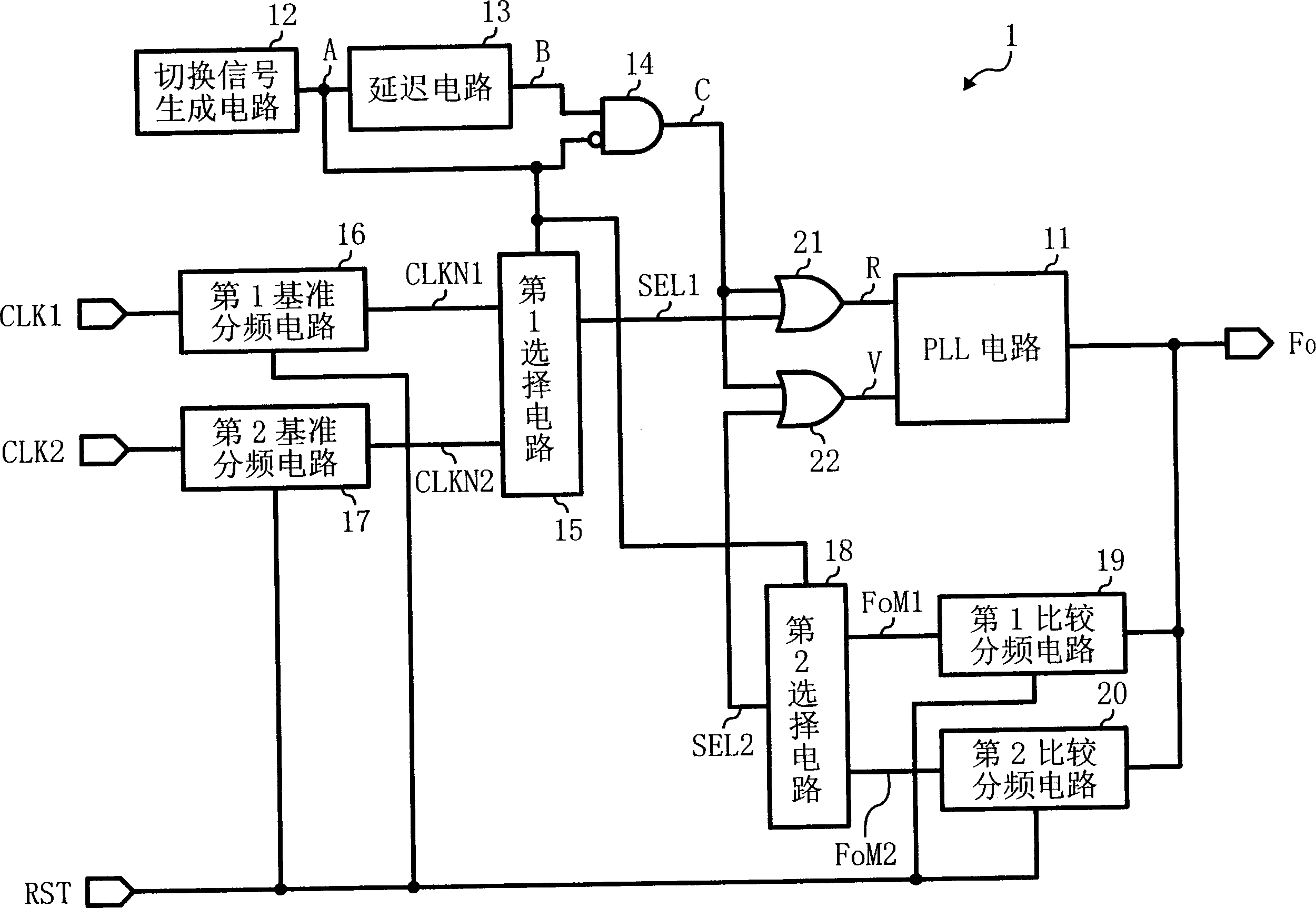
[0042] figure 1 It is a layout diagram of the clock pulse generating circuit of the first embodiment of the present invention.
[0043] exist figure 1 Among them, the clock pulse generation circuit 1 switches between the input clock pulses CLK1 and CLK2, uses the selected input clock pulse as a reference clock pulse, generates an output clock pulse Fo with a predetermined frequency based on the reference clock pulse, and outputs it. In addition, in the first embodiment of the present invention, the case where there are two input clock pulses is described as an example, and the present invention is not limited thereto. The present invention can be applied to occasions where there are plural input clock pulses. In this c...
PUM
 Abstract
Description
Claims
Application Information