Cap rotating mechanism for continuous round disc type cap rotating machine

A capping machine, a disc-type technology, applied in the direction of screw caps, etc., can solve problems such as over-tightening of the cap, scratches on the surface of the cap, and insufficient screwing of the cap.

Inactive Publication Date: 2007-03-07
SHANGHAI LONGTENG TECH
View PDF0 Cites 10 Cited by
  • Summary
  • Abstract
  • Description
  • Claims
  • Application Information

AI Technical Summary

Problems solved by technology

Although the capping mechanism of this kind of capping machine can realize the function of capping, there is the following problem: because the intermediate gear is fixed, the number of rotations of the pinion gear is also fixed when the disk rotates a circle, so the rotation The number of rotations of the capping head is also fixed when the cappin...

Method used


Image

  • Cap rotating mechanism for continuous round disc type cap rotating machine
  • Cap rotating mechanism for continuous round disc type cap rotating machine

Examples


Embodiment Construction

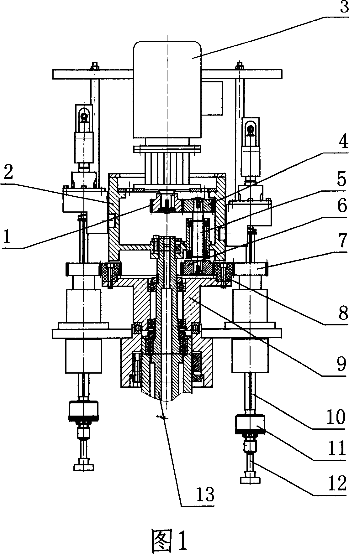
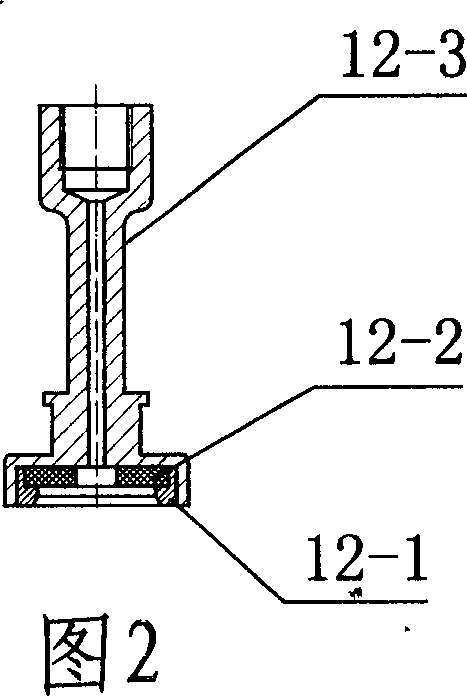
[0007] The present invention will be further described below in conjunction with the capping mechanism of 8 capping heads in conjunction with accompanying drawing:

[0008] See accompanying drawings 1 and 2, the motor reducer 3 is fixed on the middle cylindrical cam 2, the middle cylindrical cam 2 is fixed on the central fixed shaft 13 with an expansion sleeve, the reducer gear 1 is fixed on the shaft head of the motor reducer 3, The reducer gear 1 meshes with the upper gear 4, the upper gear 4, the gear shaft 5, and the lower gear 6 are fixed on the middle cylindrical cam 2 through the bearing seat, the lower gear 6 meshes with the internal teeth of the middle gear 8, and the middle gear 8 is fixed in the middle On the gear fixing seat 9, the intermediate gear fixing seat 9 is positioned on the central fixed shaft 13 through bearings, the outer teeth of the intermediate gear 8 mesh with the gear 7, the gear 7 is connected to the transmission shaft 10, the transmission shaft 10...


PUM


Abstract

The unscrewing mechanism of a consecutive disk type unscrewing device driven by electric motor speed reducer for free rotation, flexible and convenient of operation and applicable of bottles of alls kinds of specifications, comprises of electric motor speed reducer, speed reducer gear, cam of the middle cylinder, upper gear, gear shaft, lower gear, gear, middle gear, middle gear base, drive shaft, friction clutch, central fixing shaft, and unscrewing head, with speed reducer gears equipped on the shaft end of the electric motor speed reducer, and upper gears, gear shaft and lower gears equipped on the middle cylinder cam. The gear shaft fastens on the middle cylinder cam through a bearing base; the middle gear tooths with gears that connect sequentially with the drive shaft, the friction clutch and an unscrewing head.

Description

Technical field: [0001] The invention relates to the technical field of packaging machinery, in particular to an improvement of a capping mechanism on a capping machine. Background technique: [0002] The capping mechanism of the continuous disc type capping machine in the prior art is: there is an intermediate gear above the middle cylindrical cam, and the intermediate gear is connected and fixed with the central fixed shaft of the capping machine through a key. A pinion is meshed around the middle gear, and the pinion is fixed on a transmission shaft, and a capping head is fixed at the lower end of the transmission shaft. When the capping machine disc rotates, the pinion around the intermediate gear rotates around the intermediate gear, thereby driving the capping head to rotate. The middle cylindrical cam controls the pinion, drive shaft and capping head to move up and down. Although the capping mechanism of this kind of capping machine can realize the function of cappi...

Claims


Application Information

Patent Timeline
IPC IPC(8): B67B3/20
Inventor 乔野龙李正瑞乔英刘恒珍方平计国平陈金虎丁树刚
Owner SHANGHAI LONGTENG TECH
Why Eureka
Try Eureka