Supercharge Your Innovation With Domain-Expert AI Agents!

Horizontal milling-boring machine with mobile column

A technology for milling, boring and machine tools, which is applied to metal processing mechanical parts, large fixed members, manufacturing tools, etc., and can solve problems such as high cost and difficulty

Inactive Publication Date: 2007-03-07
HPT SINERGY SRL
View PDF0 Cites 9 Cited by
  • Summary
  • Abstract
  • Description
  • Claims
  • Application Information

AI Technical Summary

Problems solved by technology

[0008] - the fact that the installation area is only suitable for this exclusive use: practically, the pit always needs to be filled and the floor of the room where the machine tool is installed needs to be restored, however this will involve considerable difficulty and high cost to redo the floor, and repeat these operations including forming new pits in different areas

Method used


Image

  • Horizontal milling-boring machine with mobile column
  • Horizontal milling-boring machine with mobile column
  • Horizontal milling-boring machine with mobile column

Examples


Embodiment Construction

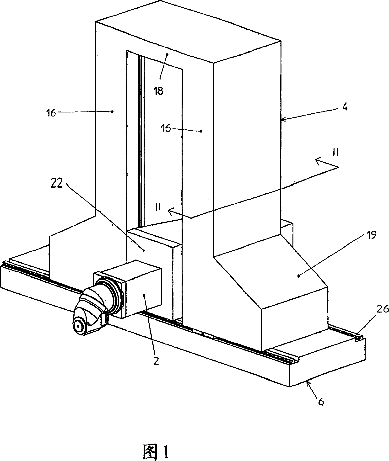
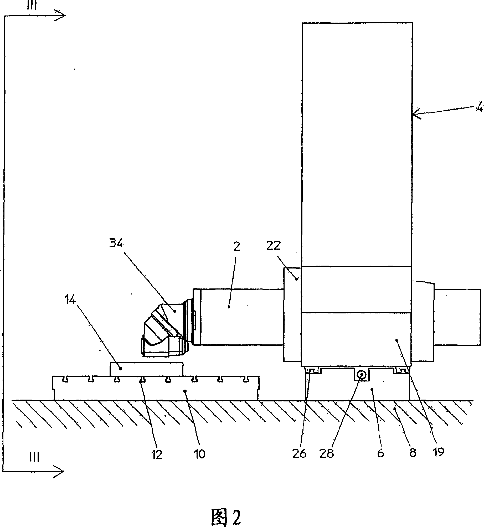
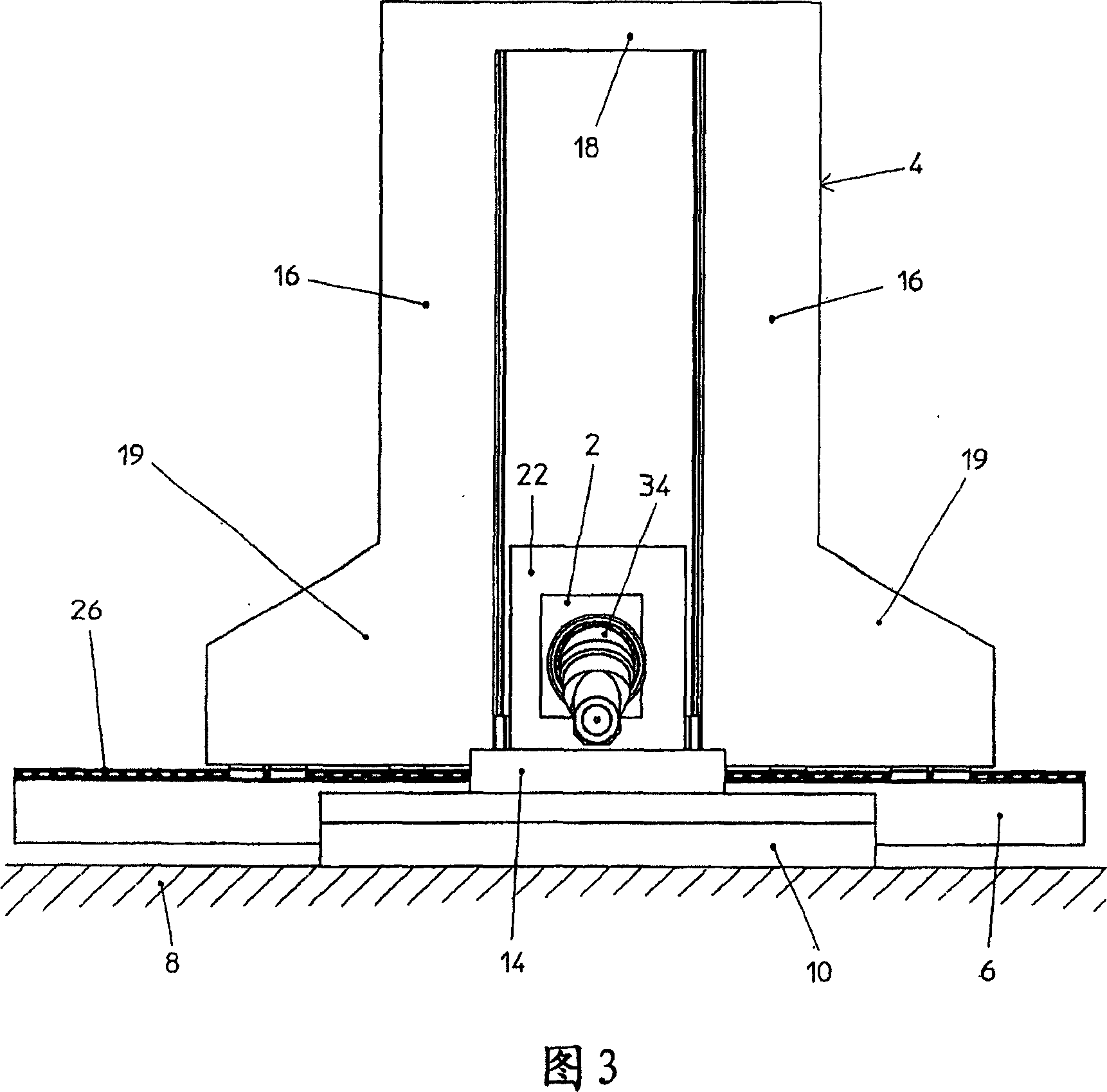
[0024] As shown in FIGS. 1-4 , the first embodiment of the milling-boring machine tool of the present invention is basically a known moving column machine tool, that is to say with a machine tool that can move axially and also vertically along the column structure 4 . The moving horizontal sliding seat 2 , the column structure itself moves horizontally along the base 6 in a direction perpendicular to the axis of the sliding block 2 , and the base 6 is anchored on the floor 8 .

[0025] More particularly, not only the base 6 is anchored to the floor 8, but also the table 10, which is separate from the base and has a recess 12, where the workpiece 14 to be machined is fixed in a conventional manner on the floor 8. On stage 10.

[0026] The column structure 4 is a symmetrical gantry type and includes a pair of columns 16. The upper part of the column 16 is connected to each other by a beam 18 and is extended into a pair of parts 19 at the lower part. The column structure on the ...


PUM


Abstract

A horizontal milling-boring machine comprising a horizontal bed (6) anchored to the floor (8), a column structure (4) supported by the bed and slidable therealong, a slide carriage (22) slidable vertically along said column structure (4), and a slide (2) supporting the tool head (34) and movable axially to said carriage (22) in a direction perpendicular to the axis of said bed (6), characterised in that: - said bed (6) is monolithic and is separated from the work table (10), - said column structure (4) is formed as a portal, with two columns (16) connected together by an upper crosspiece (18) and provided lowerly, for their support on the bed, with portions (19) lying external to the opening of said portal, which is delimited laterally by said columns (16) and extends lowerly into proximity with said bed (6), - said slide carriage (22) is slidable along the facing internal walls of said columns (16), - guide means (26) and drive means (28, 30, 32) being interposed between said column structure (4) and said bed (6).

Description

technical field [0001] The invention relates to a horizontal milling and boring machine tool with a moving column. Background technique [0002] A known mobile column milling machine comprises: a horizontal base anchored to the floor; a column support horizontally slidable along said base; a column structure supported by said support; a vertically slidable column structure along said column structure. a slide carrier; a slide seat horizontally slidable along the support in a direction perpendicular to the longitudinal axis of the base; and a spindle head mounted on the end of the slide seat and facing the worktable, the workpiece to be processed is fixed on the workbench. [0003] Recurring problems on these milling machines include base and column supports that place the spindle axis at an excessively high height from the table, which severely impedes accessibility and visibility of the workpiece being machined, especially in the taller areas of the workpiece. [0004] In...

Claims


Application Information

Patent Timeline
Patent Type & Authority Applications(China)
IPC IPC(8): B23Q1/01B23Q1/62
CPCY10T409/309576Y10T409/307728Y10T408/91B23Q1/01B23Q1/626
Inventor F·圭利G·皮科洛
Owner HPT SINERGY SRL
Features
  • R&D
  • Intellectual Property
  • Life Sciences
  • Materials
  • Tech Scout
  • Unparalleled Data Quality
  • Higher Quality Content
  • 60% Fewer Hallucinations
Learn More