
Plasma display and driving method thereof

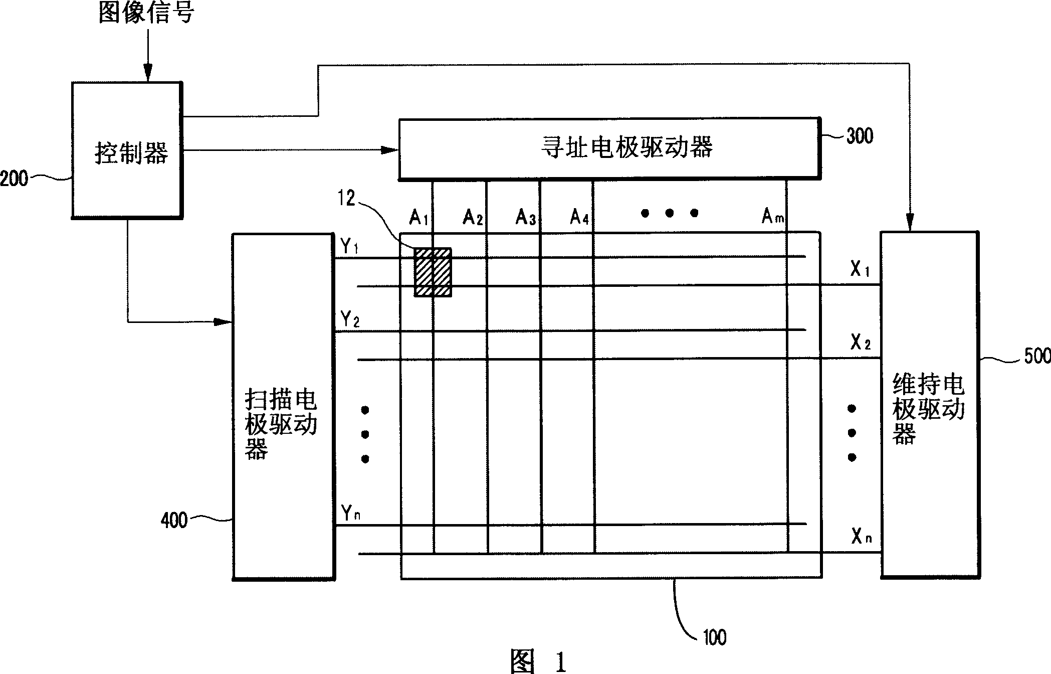
A technology of plasma and display devices, which can be used in identification devices, static indicators, televisions, etc., and can solve problems such as lengthening

Inactive Publication Date: 2007-04-25
SAMSUNG SDI CO LTD
View PDF0 Cites 0 Cited by
  • Summary
  • Abstract
  • Description
  • Claims
  • Application Information

AI Technical Summary

Problems solved by technology

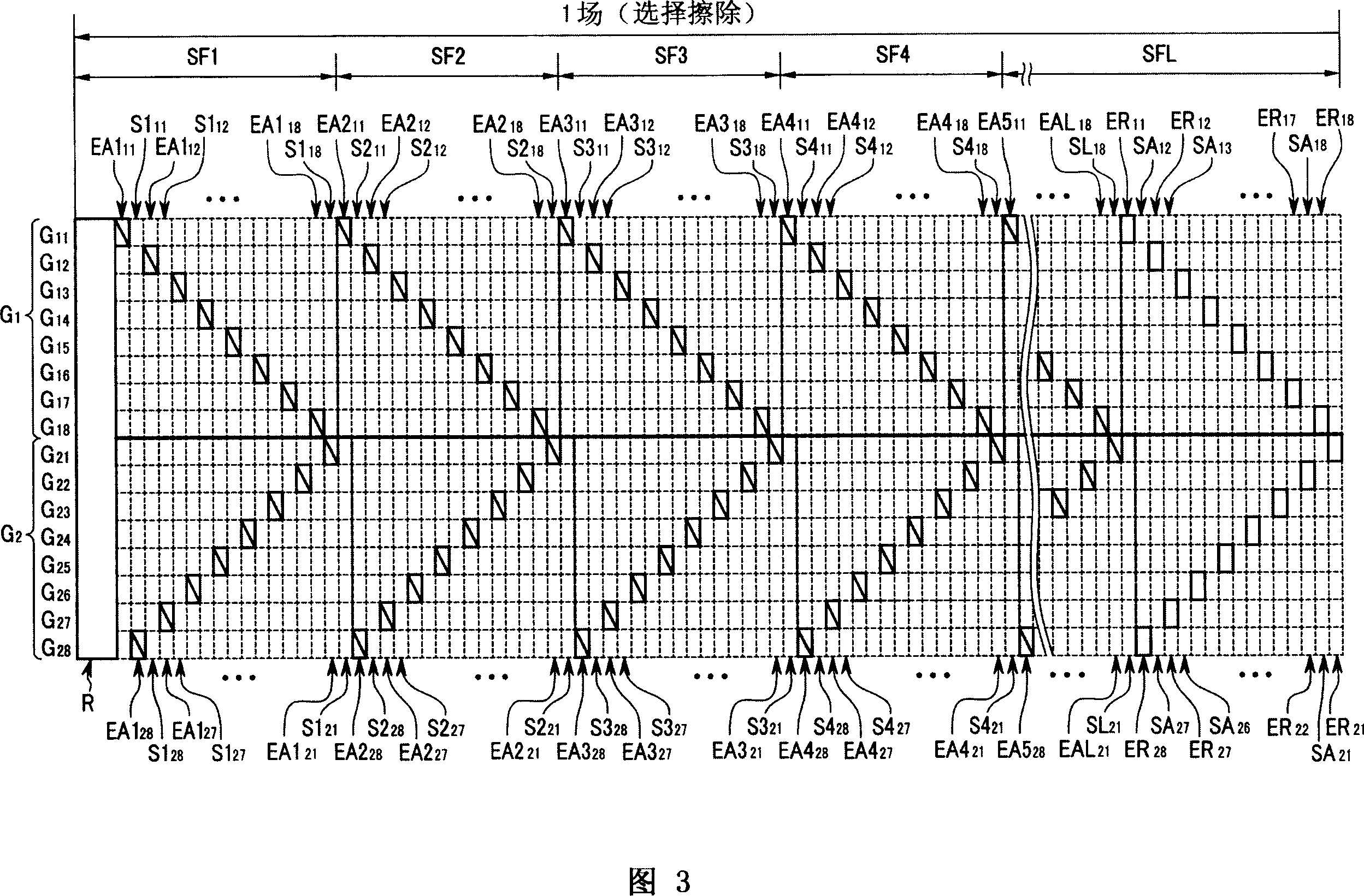
[0005] In addition, when the address period and the sustain period are separated at predetermined intervals, since each subfield has an address period for addressing all discharge cells additionally formed in addition to a sustain period for sustain discharge, one subfield the length becomes longer

Method used


Image

  • Plasma display and driving method thereof
  • Plasma display and driving method thereof
  • Plasma display and driving method thereof

Examples


Embodiment Construction

[0020] In the following detailed description, only certain embodiments of the present invention have been shown and described, simply by way of illustration. As those skilled in the art would realize, the described embodiments may be modified in various different ways, all without departing from the spirit or scope of the present invention. In order to clarify the description, specific parts not described in the specification are omitted, and specific parts provided with similar descriptions have the same reference numerals.

[0021] Furthermore, throughout the specification and claims, the word "comprising" should be understood as indicating the inclusion of stated elements, but not excluding any other elements, unless explicitly stated otherwise.

[0022] In addition, wall charges mentioned in the following description refer to charges formed and accumulated on walls (eg, dielectric layers) close to electrodes of discharge cells. Wall charges will be described as "forming" ...


PUM


Abstract

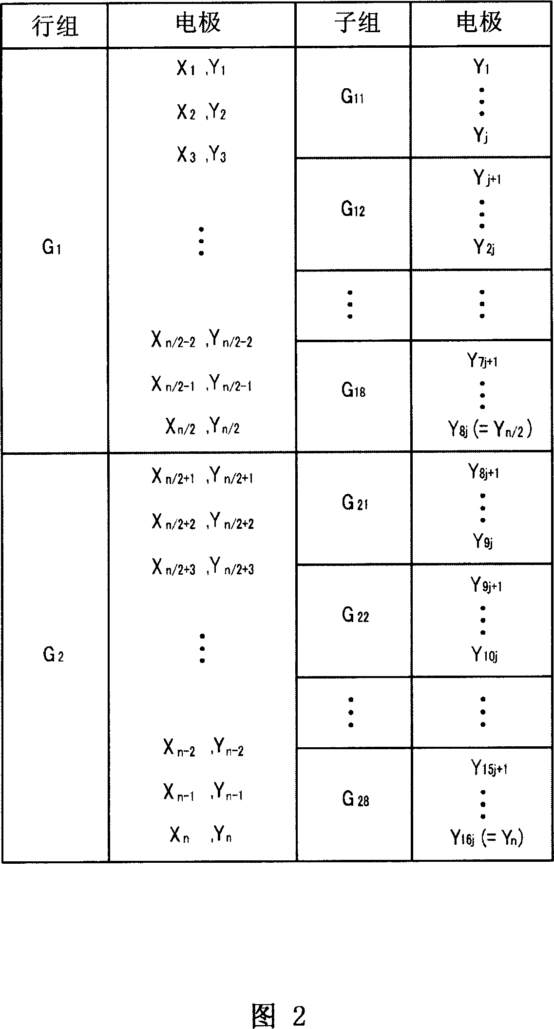
A plasma display device is driven by dividing a plurality of row electrodes into first and second row groups. A first row group of electrodes are divided into a plurality of first sub-groups, and a second row group of row electrodes are divided into a plurality of second sub-groups. During a first subfield of a first group of subfields, non-light emitting cells are selected from light emitting cells of a first sub-groups and light emitting cells of a second sub-groups are sustain-discharged during a first period. In addition, during the first subfield, the non-light emitting cells are selected from the second sub-group, and the light emitting cells of a first sub-group are sustain-discharged during a second period. With such an operation, a length of one subfield can be reduced because another row group is sustain-discharged while one row group is being selected as the non-emitting cells.

Description

technical field [0001] The invention relates to a plasma display device and a driving method thereof. Background technique [0002] A plasma display device is a flat panel display that displays characters or images using plasma generated through a gas discharge process. It includes a plurality of discharge cells arranged in a matrix pattern. [0003] On a panel of a plasma display device, a field (for example, a 1TV field) is divided into a plurality of subfields each having a weight. Gray scales are represented by a combination of weights of subfields that generate display operations among subfields. Each subfield has an addressing phase and a sustaining phase. In the addressing phase, the addressing operation selects a discharge cell that emits light and a discharge cell that does not emit light among a plurality of discharge cells. In the sustaining phase, it occurs in the selected discharge cell. The sustain discharge is performed to perform a...

Claims


Application Information

Patent Timeline
Patent Type & Authority Applications(China)
IPC IPC(8): G09G3/28G09G3/20H01J17/49G09F9/313G09G3/292G09G3/288G09G3/291G09G3/293G09G3/294G09G3/296G09G3/298H04N5/66
CPCG09G3/294G09G2310/0216G09G2320/0266G09G3/2948G09G2320/0238G09G3/2935G09G2310/0218G09G3/2932G09G3/2025G09G2320/0261G09G3/2937G09G3/296
Inventor 丁南声朴正泌韩斗渊
Owner SAMSUNG SDI CO LTD
Learn More