Video signal processing apparatus and video signal processing method

A video signal processing and video signal technology, which is applied in TV, color TV, image communication, etc., can solve the problems of insufficient effects and reduced switching impact, and achieve the effects of improving image quality, reducing switching impact, and reducing false contours

Inactive Publication Date: 2007-11-28
PANASONIC CORP
View PDF2 Cites 0 Cited by
  • Summary
  • Abstract
  • Description
  • Claims
  • Application Information

AI Technical Summary

Problems solved by technology

However, by randomly diffusing the boundary portion between the area where the moving image processing is performed and the area where the still image processing is performed with a constant width, the sharp-edged noise may remain as a gentle noise with a constant width, and the switching shock reduction effect is not sufficient.

Method used


Image

  • Video signal processing apparatus and video signal processing method
  • Video signal processing apparatus and video signal processing method
  • Video signal processing apparatus and video signal processing method

Examples


no. 1 approach

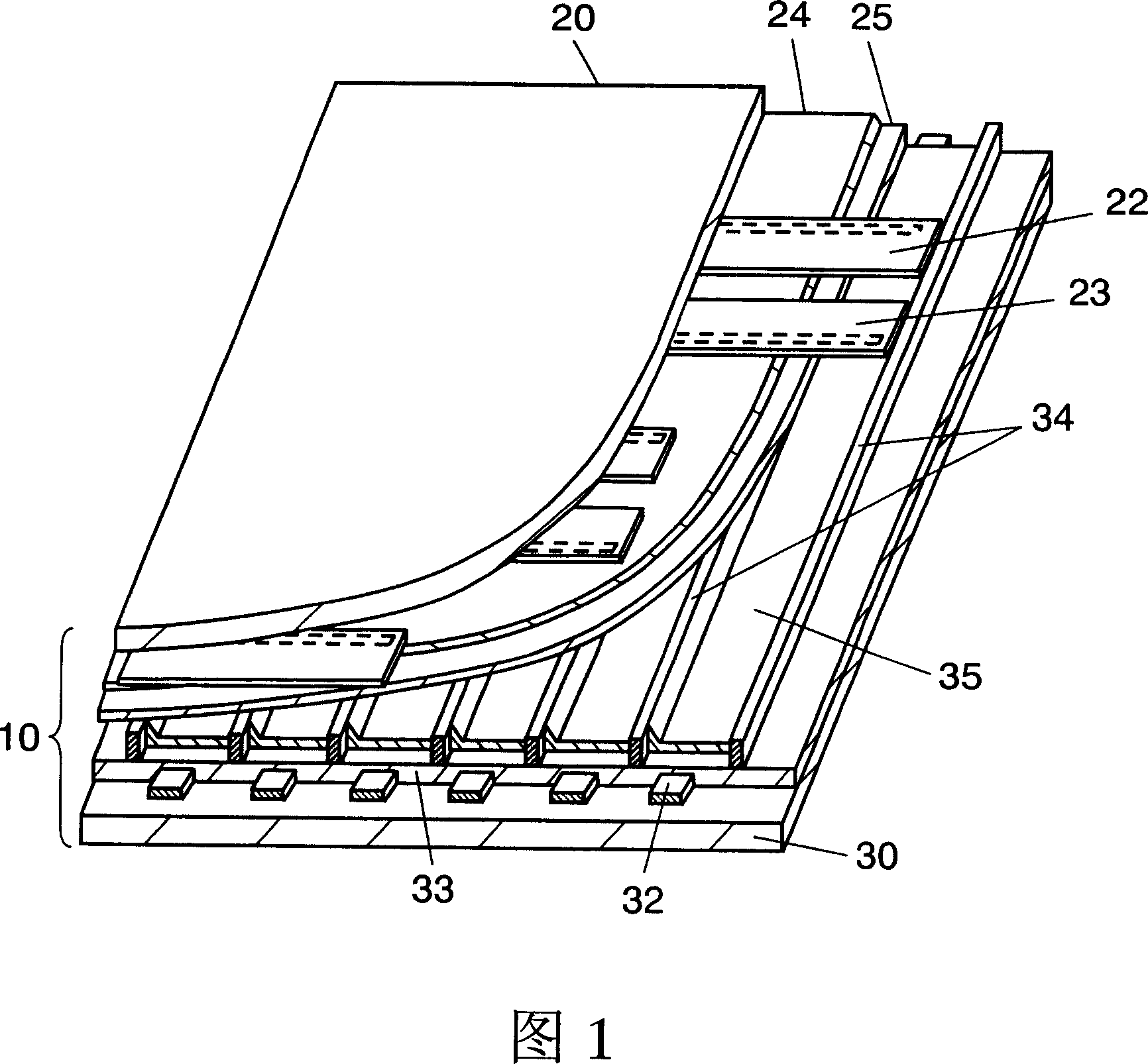
[0084] FIG. 1 is an exploded perspective view showing the structure of the PDP 10 of the plasma display device according to the first embodiment of the present invention. On the front panel 20 made of glass as the first substrate, a plurality of display electrodes composed of a pair of strip-shaped scan electrodes 22 and strip-shaped sustain electrodes 23 are formed. In addition, a dielectric layer 24 is formed so as to cover the scan electrode 22 and the sustain electrode 23, and a protective layer 25 is formed on the dielectric layer 24. On the back plate 30 as the second substrate, a plurality of strip-shaped data electrodes 32 covered by the dielectric layer 33 are formed so as to intersect the scan electrodes 22 and the sustain electrodes 23 bodies. On the dielectric layer 33, a plurality of partition walls 34 are arranged in parallel with the data electrode 32, and a phosphor layer 35 is provided on the dielectric layer 33 between the partition walls 34. In addition, the dat...

no. 2 approach

[0148] FIG. 10 is a block diagram showing the electrical structure of the transition region generating section 201 of the plasma display device according to the second embodiment of the present invention.

[0149] As shown in FIG. 10, the transition region generating unit 201 of the second embodiment of the present invention has a structure except for the selector 104, the addition unit 114, and the selector 104 that constitute the transition region generating unit 200 of the first embodiment shown in FIG. In addition to the limiter 115, a reduction unit 105 is also provided. In addition, here, the description will be focused on the reduction unit 105 that is a newly-added constituent element in the transition region generating unit 201.

[0150] The reduction unit 105, when the "still level" output from the static level delay unit 103 is less than the limiter value of the limiter 115, that is, less than the maximum value n of the "stationary level," The transition area formed by ...


PUM


Abstract

The present invention provides a video signal processing method and a video signal processing apparatus comprising a moving image region detecting part (102) that detects a moving image region from a video signal; a transition region creating part (200) that creates a transition region; a still level delaying part (103) that delays and outputs an output of the transition region creating part (200); an addition part (106) that adds an error, which has been spread from peripheral pixels, to the video signal; a still image processing part (107) that subjects the video signal to a still image process; a moving image processing part (108) that subjects the video signal to a moving image process; a selection part (300) that outputs the video signal having been subjected to the still or moving image process; a subtraction part (110) that calculates the difference between the input video signal and the output video signal; a multiplication part (111) that multiplies the error by a predetermined constant; and a delay part (112) that delays and spreads the error to the peripheral pixels. To reduce the moving image pseudo contour and also reduce the switching shock that occurs around the boundary between a moving image region and a still image region.

Description

Technical field [0001] The present invention relates to a plasma display panel (PDP, Plasma Display Panel) or a digital micro-mirror device (DMD, Digital Mirror Device), etc., which divides an image of one field into a plurality of sub-field images to perform multi-grayscale display and an image display device and image The video signal processing device and the video signal processing method in the display method. Background technique [0002] In image display devices such as PDPs or DMDs that perform image display using binary control of light emission and non-light emission, generally speaking, a so-called sub-field image is divided into a plurality of sub-field images to perform multi-gradation display. The image display of the field method. In the subfield method, one field period is divided into a plurality of subfields weighted by the number of light emission or the amount of light emission in time, and grayscale display is performed by combining the subfields of light emi...

Claims


Application Information

Patent Timeline
Patent Type & Authority Applications(China)
IPC IPC(8): G09G3/288G09G3/20G09G3/28G09G3/34H04N5/66
CPCG09G2320/0266G09G2320/103G09G3/288G09G2320/0261G09G3/2066G09G2360/16G09G3/20G09G3/296G09G3/34H04N5/66
Inventor 山田和弘
Owner PANASONIC CORP
Why Eureka
Try Eureka