Flat type discharge lamp and lighting device

A discharge lamp, a planar technology, applied in the direction of discharge lamps, gas discharge lamps, parts of gas discharge lamps, etc., can solve the problems of insufficient voltage at the front end of the lamp, decrease in lamp brightness, and decrease in lamp quality, and achieve reduction Effects of heat loss, resistance value reduction, and voltage drop suppression

Inactive Publication Date: 2007-05-02
HARISON TOSHIBA LIGHTING CORP
View PDF1 Cites 2 Cited by
  • Summary
  • Abstract
  • Description
  • Claims
  • Application Information

AI Technical Summary

Problems solved by technology

However, if the width of the electrode is narrow, it will be difficult to form a certain electrode width due to clogging of the mesh due to screen plate making when the conductive paste is printed.
Therefore, a disconnection occurs at the narrow portion of the electrode width, which causes a decrease in the quality of the lamp.
In addition, if the length of the electrode increases as the size of the lamp increases, the voltage value applied by the power supply part decreases due to the resistance loss of the electrode as the distance from the power supply part increases, and the voltage at the front end of the lamp becomes insufficient.
As a result, there is also a problem that as the distance from the power supply part decreases, the brightness of the lamp decreases, and uniform light emission cannot be obtained.

Method used


Image

  • Flat type discharge lamp and lighting device
  • Flat type discharge lamp and lighting device
  • Flat type discharge lamp and lighting device

Examples


no. 1 Embodiment

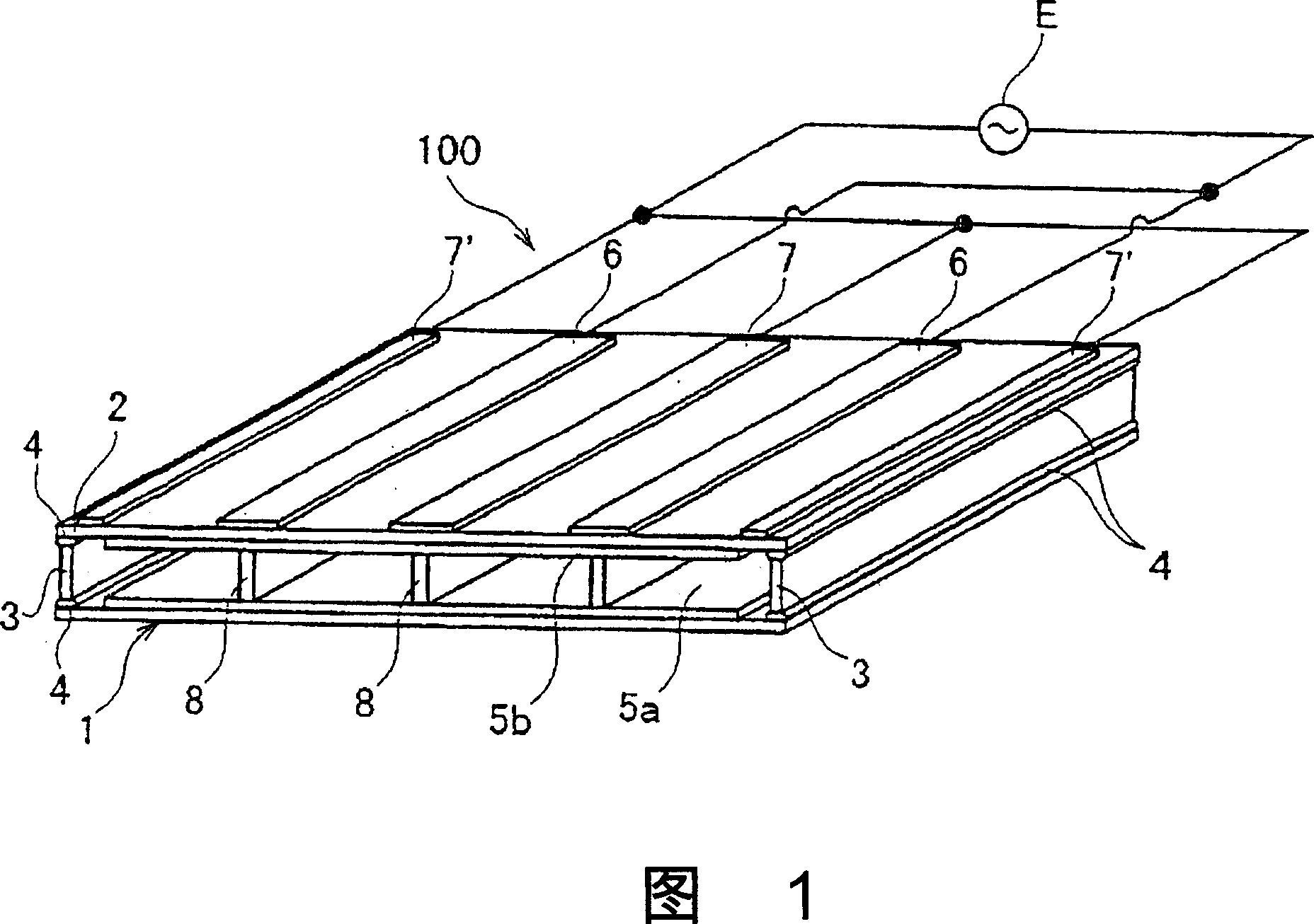
[0048] Fig. 1 is a perspective view showing a flat discharge lamp according to a first embodiment of the present invention.

[0049]The front substrate 1 and the back substrate 2 made of light-transmitting glass plates are arranged facing each other at a substantially constant interval, and the edge portions of the two glass plates are bonded by the side walls 3 with the sealing glass 4 to form a planar substrate. the discharge container. In addition, the planar container can also adopt a structure in which any one of the glass substrates is formed in a basin shape, thereby omitting the side wall, or instead of using sealing glass, the edge part of the glass substrate is heated to melt the glass and bonded. up structure.

[0050] Inside the planar discharge vessel, as a discharge medium, one or a mixture of two or more of mercury vapor, xenon, krypton, argon, neon, and helium is filled at an inflation pressure of several kPa to hundreds of kPa.

[0051] Fluorescent layers 5a...

no. 2 Embodiment

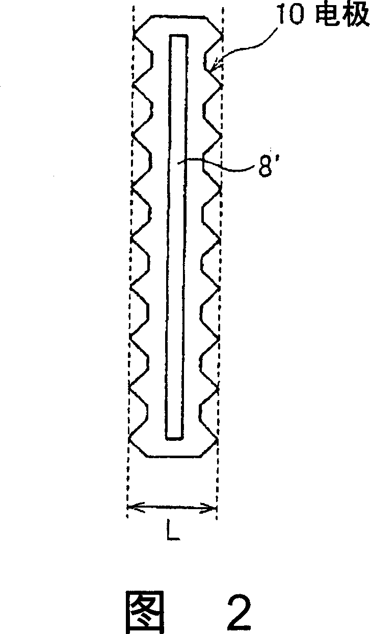
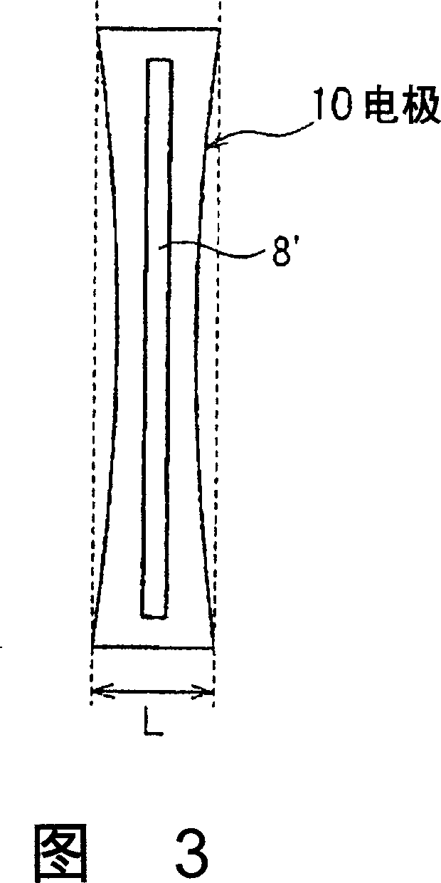
[0060] 15 to 17 respectively show a perspective view, a plan view, and a cross-sectional view of a flat discharge lamp 20 according to a second embodiment of the present invention. In addition, FIG. 18 is a sectional view taken along line A-A' in FIG. 16 . Between the front substrate 1 and the rear substrate 2, a spacer 8 is formed in a hollow cylindrical shape such as a cylindrical shape or a quadrangular cylindrical shape to prevent collapse due to atmospheric pressure. Utilize front substrate 1 and back substrate 2 and side wall 3 (though not shown in figure, but be formed on the 4 sides of front substrate 1 and back substrate 2), keep the airtightness in the discharge vessel, at least fill the inside with mercury vapor or More than one inert gas is used as the discharge medium.

[0061] In addition, the airtightness of the interior of the hollow spacer 8 should also be maintained, and mercury vapor or more than one inert gas should also be filled. Here, the inert gas in ...

no. 3 Embodiment

[0064] 19 and 20 are perspective views of a flat discharge lamp 20 according to a third embodiment of the present invention, and are perspective views of the flat discharge lamp 20 viewed from the rear substrate 2 and the front substrate 1, respectively.

[0065] In this embodiment, the front substrate 1 made of a light-transmitting glass plate is thermoformed to have a concavo-convex cross-section, and the convex portion 1b is in contact with the back substrate 2 also made of a light-transmitting glass plate. function as a spacer. That is, between the front substrate 1 and the rear substrate 2 , a plurality of elongated discharge spaces are formed by full-shaped recesses. Then, elongated strip-shaped external electrodes 6 and 7 are formed on the outer surface of rear substrate 2 . Then, the structure is the same as that of the first embodiment, and the bonding surface between the convex portion 1b of the front substrate 1 and the rear substrate 2 is provided within the maxim...


PUM


Abstract

A front substrate (1) and a rear substrate (2) composed of translucent sheets of glass are disposed to face each other with an almost constant interval, and the peripheral portions of the two sheets of glass are bonded together with frit glass (4) via side walls (3) to form a flat discharge container. Fluorescent substance layers (5a, 5b) are formed on the inner sides of the front substrate (1) and the rear substrate (2) to convert a ultraviolet ray emitted from a discharge medium into a visible light. External electrodes (6) for applying high voltage and external electrodes (7) for applying low voltage are alternately arranged on the outer surface of the rear substrate (2). A plurality of slender spacers (8) are arranged between the front substrate (1) and the rear substrate (2) at constant intervals to keep constant the space between the front substrate (1) and the rear substrate (2) and prevent damage due to lamp implosion to be caused by pressure difference between the inside and outside of the discharge container. A linear spacer (8) is disposed so as to be contained within the maximum width of an external electrode (6), and one electrode (6) is apparently divided into two pieces. One electrode (6) is exposed to respective discharge spaces divided by a linear spacer (8), and is allowed to work as electrodes (10) in respective discharge spaces, whereby it is possible to stably light up respective discharge spaces.

Description

technical field [0001] The invention relates to a flat discharge lamp and a lighting device. Background technique [0002] Recently, with the increase in size of liquid crystal displays, as a fluorescent lamp used as a backlight light source, a flat type discharge lamp in which a discharge space is formed in a flat-shaped sealed glass container has been developed. This type of flat discharge lamp forms a fluorescent film on the inner surface of the glass container, and fills the flat discharge space with a mixture of inert gases such as xenon, neon, and argon, or a mixture of these gases and mercury vapor. composition of the discharge medium. A plurality of strip-shaped discharge electrodes parallel to each other are formed on the upper and lower outer surfaces of the flat glass container. [0003] Given a necessary potential difference between adjacent discharge electrodes formed on the outer surface of the glass container, discharge occurs throughout the entire discharge...

Claims


Application Information

Patent Timeline
Patent Type & Authority Applications(China)
IPC IPC(8): H01J65/00H01J61/30
CPCH01J61/305H01J65/00
Inventor 矢野英寿久津那庆一
Owner HARISON TOSHIBA LIGHTING CORP
Why Eureka
Try Eureka