Pre-directing insert for a bi-directional exhausting handheld planer

A manual and insert technology, applied in manual planing, metal processing machinery parts, manufacturing tools, etc., can solve problems such as blockage of chip outlets

Inactive Publication Date: 2007-05-30
TECHTRONIC IND CO LTD
View PDF0 Cites 11 Cited by
  • Summary
  • Abstract
  • Description
  • Claims
  • Application Information

AI Technical Summary

Problems solved by technology

However, in a two-way hand planer, where the airflow from the motor flows through the frame in a direction transverse to the longitudinal axis of the hand planer, the two-way hand planer typically has a tendency for debris to clog the chip outlet opposite the normal airflow direction. question

Method used


Image

  • Pre-directing insert for a bi-directional exhausting handheld planer
  • Pre-directing insert for a bi-directional exhausting handheld planer
  • Pre-directing insert for a bi-directional exhausting handheld planer

Examples


Embodiment Construction

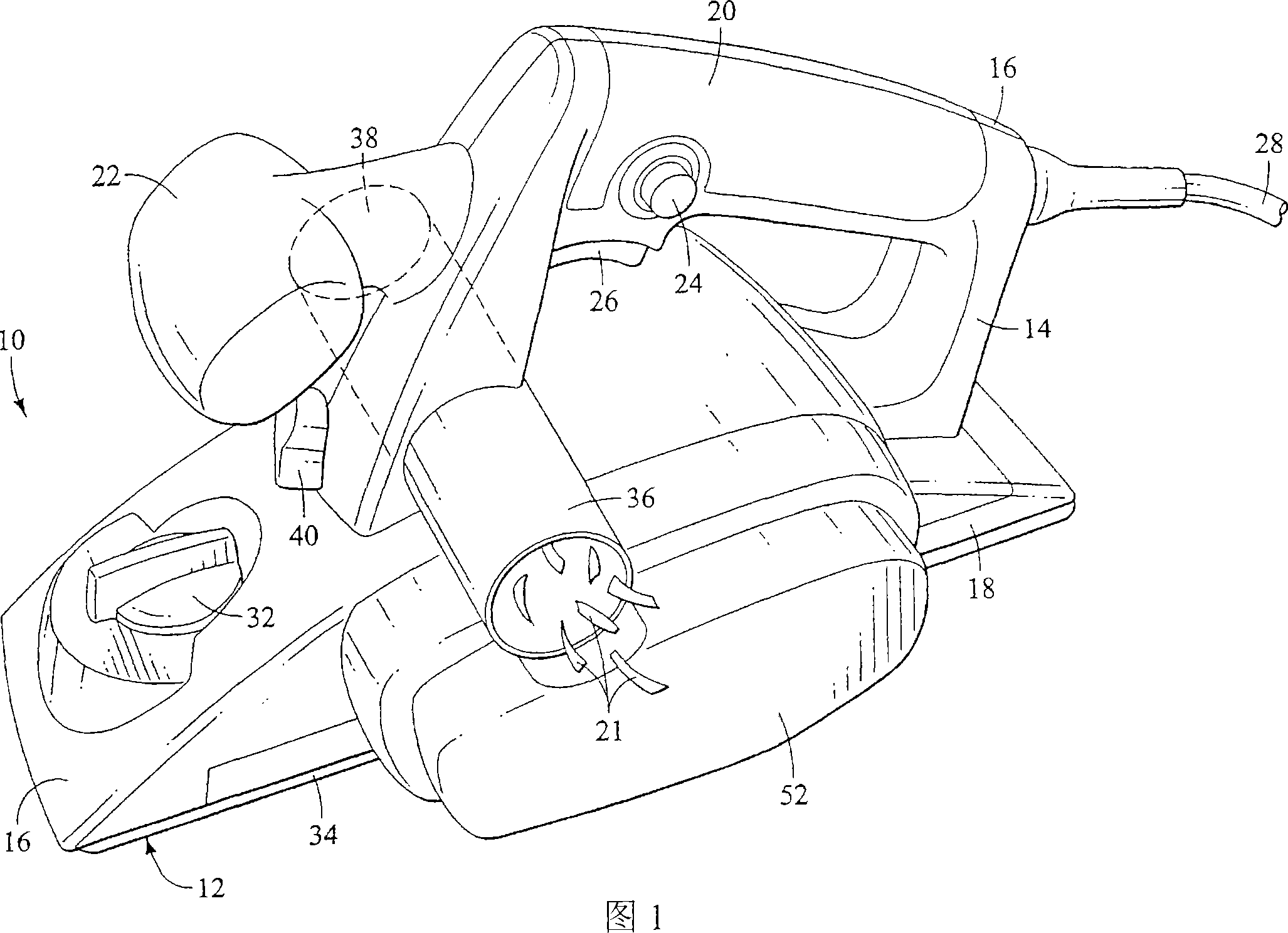
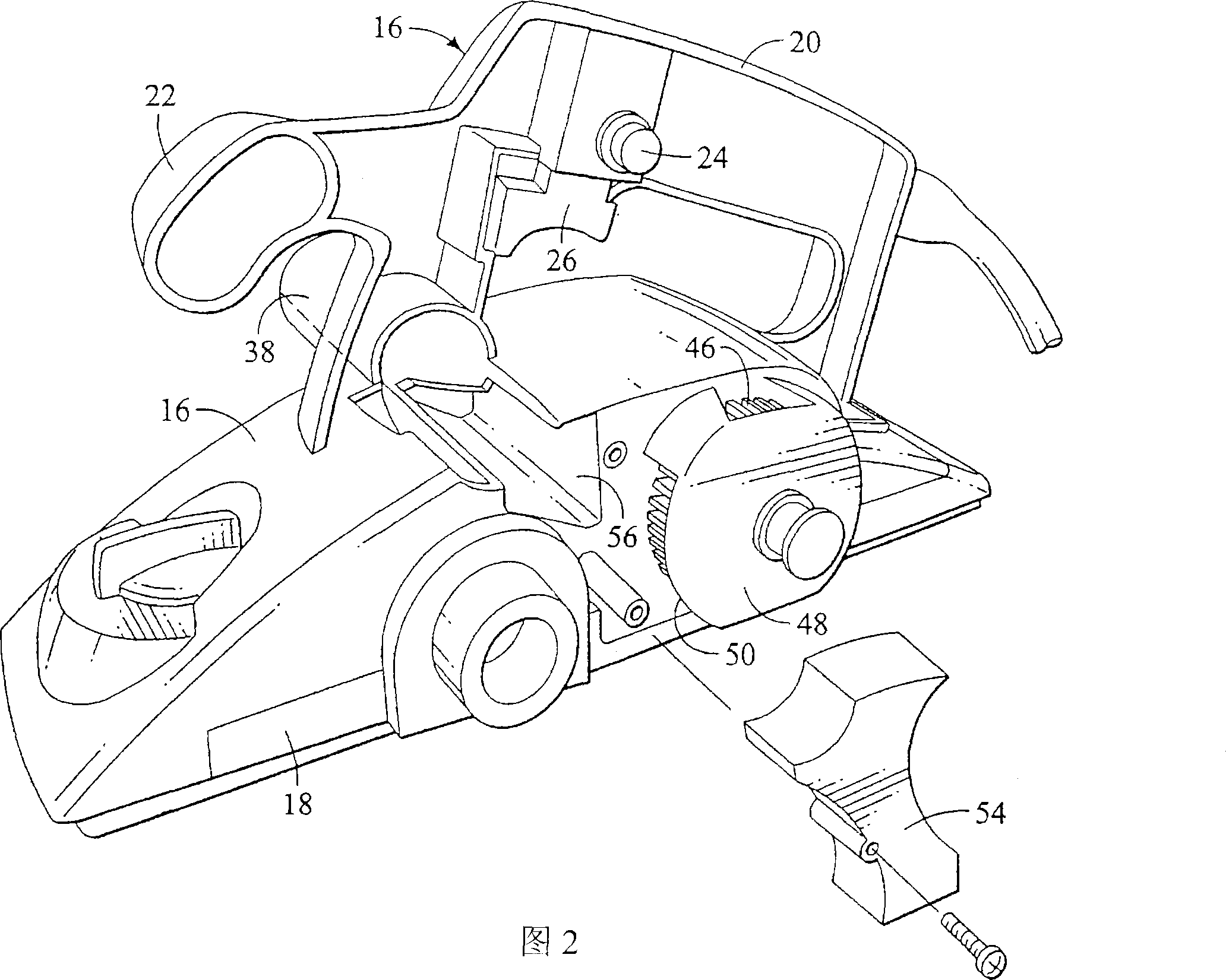
[0018] FIG. 1 is a top perspective view of one embodiment of a bi-directional chip removal hand planer 10 . The planer 10 includes a main body frame 12 having a first portion 14, a second portion 16 and a third portion 18, wherein the first and second portions 14, 16 divide the handle portion of the frame 12 into As shown in FIG. 2, the third portion 18 is disposed vertically below the first and second portions 14, 16 with the first portion 14 removed. The planer 10 includes a rear handle 20 and a front handle 22 . The rear handle 20 is oriented in the longitudinal direction of the planer 10 . In this embodiment, the front handle 22 is oriented transversely of the planer 10 , forward in the longitudinal direction, and is disposed vertically below the rear handle 20 . The rear handle 20 includes a safety button 24 and a trigger 26 for starting a motor 27 ( FIGS. 5A-5B ).

[0019] Both handles 20 and 22 allow a user to control the movement and direction of planer 10 . By hol...


PUM


Abstract

A bi-directional handheld planer is used to remove chips from a workpiece in order to make the surface planar. The handheld planer allows the user to choose between a pair of opposing exhaust ports from which the chips are to be expelled from the planer. Particular handheld planers have a normal direction of air flow that is transverse to the longitudinal direction of the planer. The bi-directional handheld planer provides for exhaustion of the chips through either of a pair of exhaust ports, and an insert (66) can be disposed within the cutting chamber (58) to pre-direct the chips toward one of the exhaust ports in order to prevent the clogging of the exhaust port which caused by the turbulence and constant contact of the chips being re-directed in the direction opposite the normal flow of air through the housing of the planer.

Description

Background technique [0001] The invention relates to the field of manual planing, and more specifically, relates to a bidirectional chip removal manual planer. [0002] Portable hand planers are used to smooth uneven surfaces on workpieces by chipping away raised portions from the workpiece until the surface of the workpiece is fairly smooth. Hand planing utilizes a high-speed rotating cutting tool having at least one blade configured to cut and remove debris from a workpiece until a smooth surface is achieved. The blades are located within the frame of the hand planer and extend from within the frame to contact the surface of the workpiece to be planed. The extent to which the blade extends beyond the frame can be adjusted to provide a cut deeper into the workpiece so that more of the workpiece is removed as the cutting tool rotates. When removing debris from a workpiece, the debris is usually discharged from the hand planer through a chip discharge port located on the side...

Claims


Application Information

Patent Timeline
Patent Type & Authority Applications(China)
IPC IPC(8): B27C1/10B23Q11/00
CPCB27C1/10
Inventor W·E·凯泽
Owner TECHTRONIC IND CO LTD
Why Eureka
Try Eureka