Feeding device for sewing machine
A technology of feeding device and sewing machine, which is applied in the direction of sewing machine components, sewing equipment, cloth feeding mechanism, etc., can solve the problems such as poor workability of differential ratio adjustment, and achieve the effect of increasing output angle and increasing output angle difference
- Summary
- Abstract
- Description
- Claims
- Application Information
AI Technical Summary
Problems solved by technology
Method used
Image
Examples
Embodiment 1
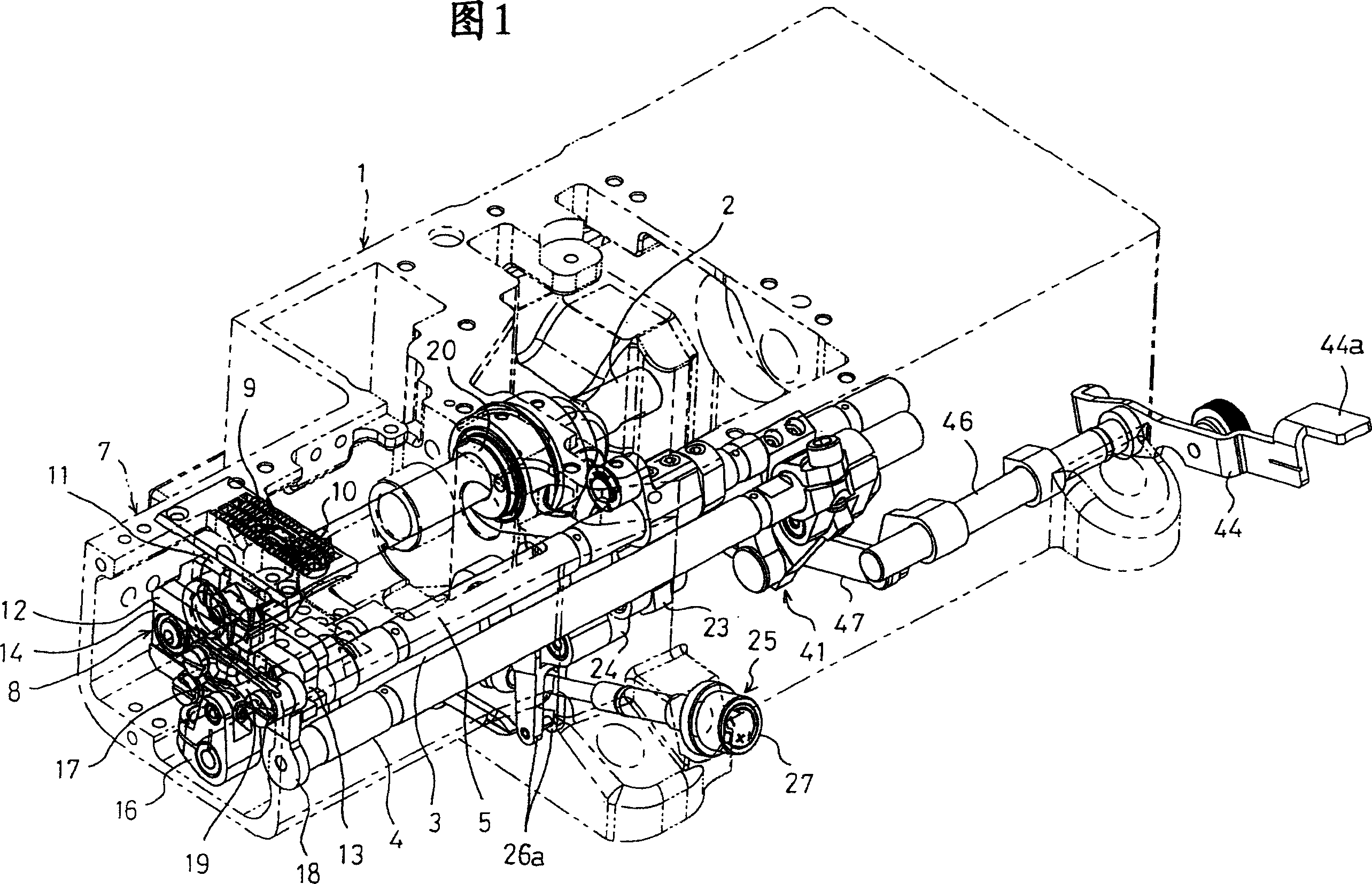
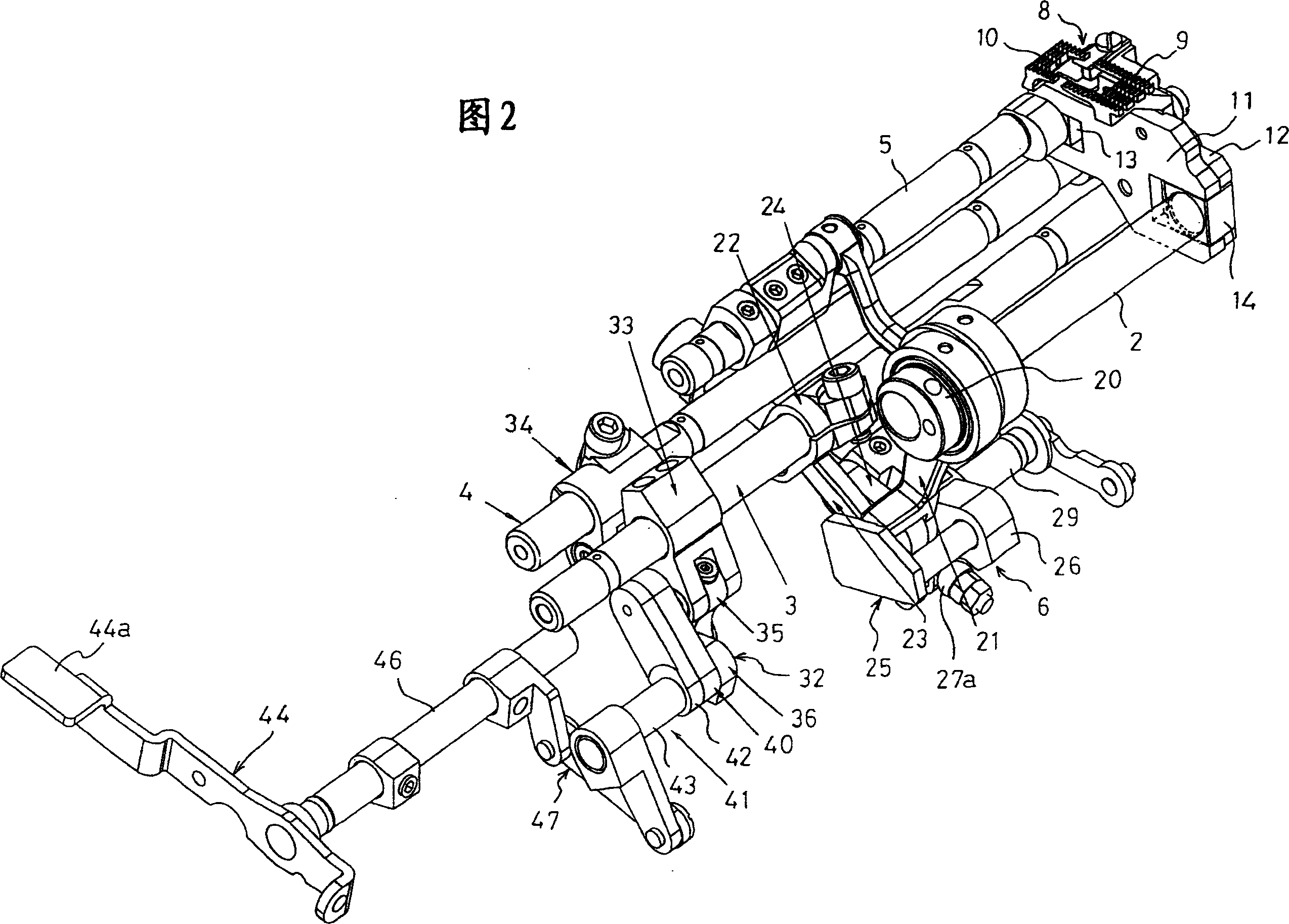
[0063] In Embodiment 1, the above-mentioned intermediate portion P is set at the connection point portion 37 of the second differential feed link 36 and the second differential feed arm 34 , and is connected with the differential feed adjustment. The connecting point portion 38 of the lever 40 is shifted closer to the position P1 of the connecting point portion 37 of the second differential feed arm 34 than the central position P3 on the line L of the connecting point portion 38 .
[0064] Therefore, as shown in Figure 9, when the support shaft 45 is at position A; when the differential feed adjustment lever 44 as shown in Figure 6 is at position A[1:0.6], if the main feed shaft 3 is only swung by 35° , the differential feed shaft 4 only swings 1.37°, if the main feed shaft 3 only swings 45°, the differential feed shaft 4 only swings 3.19°. That is, when the pivot 45 is at the A position and the rotation angle (input angle) of the main feed shaft 3 is 10°, the swing angle of t...
Embodiment 2
[0068] In Example 2, the above-mentioned intermediate portion P is set on the second differential feed link 36 in a direction away from the main feed shaft 3 and the differential feed shaft 4 compared with the above-mentioned line L. In addition, it is the same as that of Embodiment 1 (the position of the main feed shaft 3, the position of the differential feed shaft 4, the position of the differential feed adjustment shaft 43, the swing start of the main feed shaft 3 position, the swing start position of the differential feed shaft 4 , the positions A and B of the support shaft 45 , the first and second differential feed arms 33 and 34 , etc.) are implemented in the same manner.
[0069] Therefore, the same as the case of Embodiment 1, as shown in Figure 10, when the fulcrum 45 is at position A; when the differential feed adjustment lever 44 as shown in Figure 6 is at position A[1:0.6], if the main The feed shaft 3 only swings 35°, and the differential feed shaft 4 only swing...
Embodiment 3
[0073] In Example 3, the same implementation as in Example 1 was performed except that the middle portion P was set at the center position P3 on the line L of the second differential feed link 36 .
[0074] Therefore, the same as the case of Embodiment 1, as shown in Figure 11, when the fulcrum 45 is at position A; when the differential feed adjustment lever 44 as shown in Figure 6 is at position A[1:0.6], if the main The feed shaft 3 only swings 35°, and the differential feed shaft 4 only swings 1.16°. If the main feed shaft 3 only swings 45°, the differential feed shaft 4 only swings 3.10°. That is, when the pivot 45 is at the A position and the rotation angle (input angle) of the main feed shaft 3 is 10°, the swing angle of the differential feed shaft 4 is 3.10°+1.16°=4.26°.
[0075]When the support shaft 45 is at the position D; the differential feed adjustment lever 44 is at the position D[1:1.8], if the main feed shaft 3 only swings 35°, the swing angle of the differenti...
PUM
 Abstract
Description
Claims
Application Information
 - R&D
- Intellectual Property
- Life Sciences
- Materials
- Tech Scout
- Unparalleled Data Quality
- Higher Quality Content
- 60% Fewer Hallucinations
Browse by: Latest US Patents, China's latest patents, Technical Efficacy Thesaurus, Application Domain, Technology Topic, Popular Technical Reports.
© 2025 PatSnap. All rights reserved.Legal|Privacy policy|Modern Slavery Act Transparency Statement|Sitemap|About US| Contact US: help@patsnap.com


