
Improved manufacturing for virtual and augmented reality systems and components

A diffractive optical element and pattern technology, applied in optical elements, optical elements, instruments, etc., can solve the problems of eye fatigue, unstable imaging, adaptability conflict of human visual system, etc., achieve a uniform base layer, and increase the output angle of the grating , the effect of increasing the angle

Active Publication Date: 2017-12-01
MAGIC LEAP INC
View PDF8 Cites 5 Cited by
  • Summary
  • Abstract
  • Description
  • Claims
  • Application Information

AI Technical Summary

Problems solved by technology

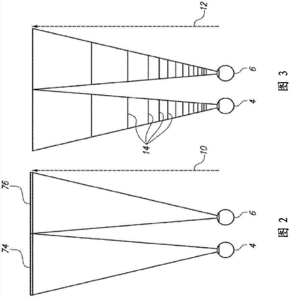
If the adaptive response to a displayed point does not correspond to the virtual depth at that point, as determined by convergence and binocular depth cues for stereopsis, the human visual system may experience adaptive conflict, resulting in unstable imaging, deleterious Eye strain, headaches, and, in the absence of adaptive information, an almost total non-existence of surface depth

Method used


Image

  • Improved manufacturing for virtual and augmented reality systems and components
  • Improved manufacturing for virtual and augmented reality systems and components
  • Improved manufacturing for virtual and augmented reality systems and components

Examples


Embodiment Construction

[0048] According to some embodiments of the present invention, a diffractive structure including an underlayer / intermediate layer between the waveguide substrate and the top grating surface is adopted. The top grating surface includes a first material corresponding to a first refractive index value, the underlying layer includes a second material corresponding to a second refractive index value, and the substrate includes a third refractive index value The third material.

[0049] One advantage of this method is that the appropriate choice of the relative refractive index of the three layers allows the structure to obtain a larger field of view for a larger range of incident light, because the lowest total internal reflection angle increases with the refractive index. Big and reduce. The diffraction efficiency can be increased, allowing "brighter" light to be output to the display of the image viewing device.

[0050] Various combinations can be used, in which an underlying layer...


PUM

PropertyMeasurementUnit
diameteraaaaaaaaaa

Abstract

Disclosed is an improved diffraction structure for 3D display systems. The improved diffraction structure includes an intermediate layer that resides between a waveguide substrate and a top grating surface. The top grating surface comprises a first material that corresponds to a first refractive index value, the underlayer comprises a second material that corresponds to a second refractive index value, and the substrate comprises a third material that corresponds to a third refractive index value. According to additional embodiments, improved approaches are provided to implement deposition of imprint materials onto a substrate, which allow for very precise distribution and deposition of different imprint patterns onto any number of substrate surfaces.

Description

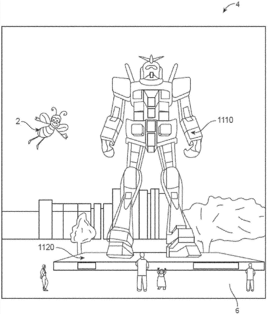
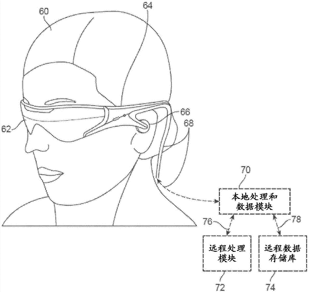
Technical field [0001] The present disclosure relates to virtual reality and augmented reality imaging and visualization systems. Background technique [0002] Modern computing and display technologies have facilitated the development of systems for so-called "virtual reality" or "augmented reality" experiences, in which digitally reproduced images or parts of them are presented to users in a way that looks lifelike or can be perceived as lifelike. Virtual reality or "VR" scenarios generally involve the presentation of digital or virtual image information, but the actual real-world visualization input cannot be seen; augmented reality or "AR" scenarios generally involve the presentation of digital or virtual image information as a visual enhancement of the actual world around the user . For example, refer to figure 1 , Describes an augmented reality scene (4), where users of AR technology see a real-world setting (6) similar to a park, which features people, trees, buildings in ...

Claims


Application Information

Patent Timeline
Patent Type & Authority Applications(China)
IPC IPC(8): G02B5/00G02B5/18
CPCG02B27/017G02B5/1857G02B27/4205G02B2027/0178B29D11/00355B29D11/00432B29D11/00682G02B5/1823G02B5/1842G02B5/1852G02B27/0172G02B2027/0112
Inventor R·D·泰克尔斯特M·A·克鲁格P·M·格列柯B·T·朔文格特
Owner MAGIC LEAP INC
Learn More