optical projection screen

An optical projection and screen technology, applied in the screen field, can solve the problems of not improving color saturation and black-and-white contrast, low color saturation of images, and narrow viewing angle, so as to avoid the interference of external light and achieve high color saturation , the effect of increasing the gain value

Inactive Publication Date: 2011-11-30
ZHEJIANG MINGPIN PHOTOELECTRIC NEW MATERIAL
View PDF8 Cites 14 Cited by
  • Summary
  • Abstract
  • Description
  • Claims
  • Application Information

AI Technical Summary

Problems solved by technology

[0006] 1. Poor light resistance
[0007] The traditional projection screen 1 is easy to diffuse or reflect other light sources around, so when projecting, it needs to be in a relatively dark environment to get a better visual effect, so the light resistance is poor
[0008] 2. High gain but narrow viewing angle
[0009] Although the U.S. Patent No. 6,747,796 can increase the gain value of the traditional projection screen 1 and improve its light resistance, it is also easy to refract other external light because of its circular surface structure, so that the viewing angle is between 40 and 70 degrees. Only the gain value can be significantly increased, so the viewing angle becomes quite narrow
[0010] 3. The use environment is limited
[0013] Due to the reflection and refraction of external light, and there is no function to improve color saturation and black-and-white contrast, the image presented is low color saturation and low black-and-white contrast

Method used


Image

  • optical projection screen
  • optical projection screen
  • optical projection screen

Examples


Embodiment Construction

[0039] The aforementioned and other technical contents, features and effects of the present invention will be clearly presented in the following detailed description of a preferred embodiment with reference to the drawings.

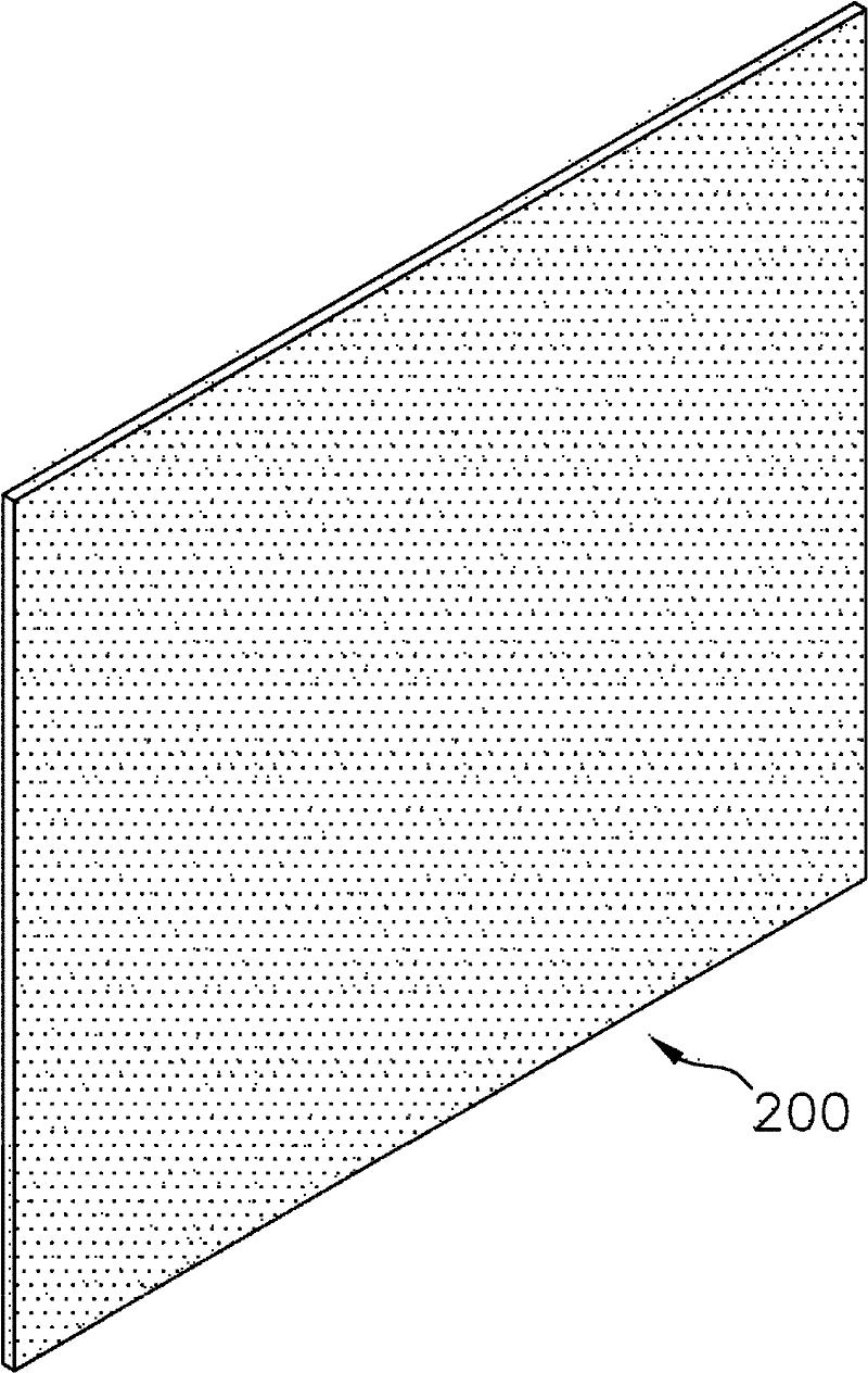
[0040] refer to image 3 and Figure 4 , is a preferred embodiment of the optical projection screen 200 of the present invention. This preferred embodiment comprises a base film 2, a base film 3 positioned at the bottom of the base film 2, a lens layer 4 formed on the base film 2, a reflective layer 5 formed on the lens layer 4, a A surface film 6 on the reflective layer 5, a diffusion layer 7 formed on the surface film 6, an anti-glare anti-scratch layer 72 formed on the diffusion layer 7, and two layers respectively located on the base film 2 and The bottom film 3 and the pressure-sensitive adhesive layer 8 between the reflective layer 5 and the surface film 6 .

[0041] The base film 3 has an opaque paint portion 31 adjacent to the base film 2 and a...


PUM


Abstract

An optical projection screen comprises a basal film, a lens layer, a reflecting layer, a surface film and a diffusion layer; wherein the lens layer is formed on the basal film and provided with a plurality of micro lens structures; the reflecting layer is formed on the lens layer; the surface film is arranged on the reflecting layer; and the diffusion layer is formed on the surface film and provided with a plurality of nano-scale black particles, a surface of the diffusion layer is in an uneven shape, thus the diffusion layer has a glare-resistant function and a scratch-resistant function. The reflecting layer reflects an incident light coming from a projector into an emergent light, a gain value of the emergent light can be raised and a reflection angle of the emergent light can be increased via the reflecting layer, then the uneven surface of the diffusion layer is utilized to diffuse the emergent light and avoid interferences of external lights, thus the optical projection screen may have a good light resistance and a high gain, and a half gain visual angle of the optical projection screen can reach more than 175 degrees.

Description

technical field [0001] The invention relates to a screen, in particular to an optical projection screen with good light resistance, high black-and-white contrast, high gain, and a half-gain viewing angle of more than 175 degrees. Background technique [0002] refer to figure 1 The projection screen 1 is generally used in movie theaters, meeting rooms, and home theaters, and the projection light 12 from a projector 11 is presented on the projection screen 1 in a diffuse or reflective manner. When the direction of the projection light 12 is fixed and the luminous flux is constant, the ratio of the brightness of the diffused and reflected beams of the projection screen 1 to the projection light 12 is called the gain of the projection screen 1 (Gain). In the horizontal direction, the gain value of the projection screen 1 gradually decreases from the center to the outside, and an angle at which the half gain value (Half Gain) can be viewed is defined as the half gain viewing ang...

Claims


Application Information

Patent Timeline
Patent Type & Authority Applications(China)
IPC IPC(8): G03B21/62G02B5/02G03B21/602
Inventor 简铭镇简佑玮
Owner ZHEJIANG MINGPIN PHOTOELECTRIC NEW MATERIAL
Why Eureka
Try Eureka