Light emitting device

Inactive Publication Date: 2011-10-20
PHOENIX ELECTRIC CO
View PDF2 Cites 15 Cited by
  • Summary
  • Abstract
  • Description
  • Claims
  • Application Information

AI Technical Summary

Benefits of technology

[0043]The peripheral light L2 from the point light source 14 becomes almost like the light emitted from a “point” light source smaller than the real light-emitting area. Consequently, “the accuracy of convergence” of the peripheral light L2 emitted from the light-emitting opening 20 of the reflector 12 is improved.
[0044]Furthermore, as well as the light emitting device according to the first aspect of the present invention, the peripheral light L2 is refracted and diffused into a direction that the angle between the light L2 and the light axis L becomes larger with the concave lens part 36. The peripheral light L2 foll

Problems solved by technology

But even the light emitting device according to the Patent Document 1, it is not

Method used


Image

  • Light emitting device
  • Light emitting device
  • Light emitting device

Examples


Embodiment Construction

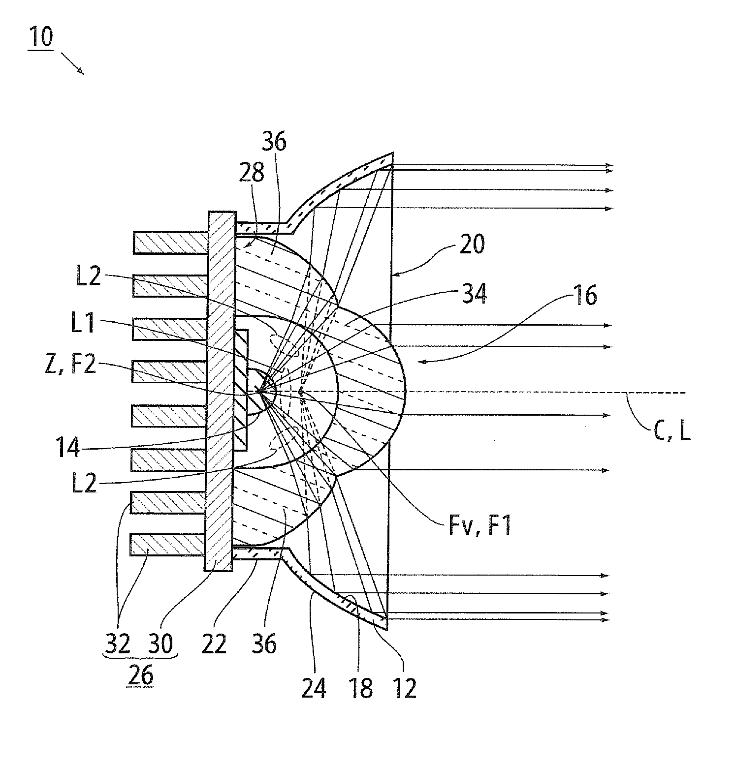
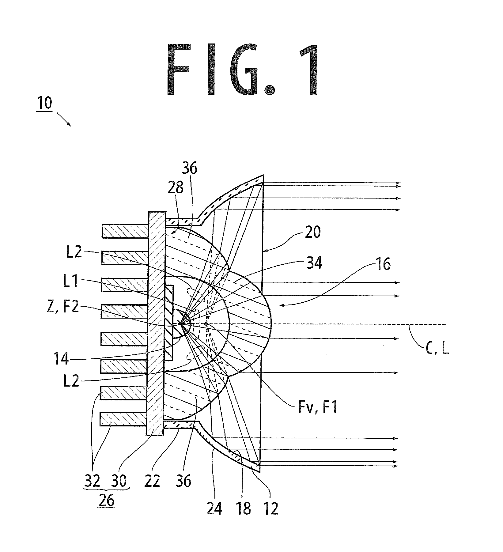
[0050]A light emitting device 10 according to the present invention is explained with figures as below. The light emitting device 10 comprises: a reflector 12, a heat sink 26 for absorption and radiation of heat, a point light source 14, and a combined lens 16.

[0051]The reflector 12 has a concave reflecting surface 18 formed inside, a light-emitting opening 20 through which light from the point light source 14 is emitted, and an almost cylindrical center cylindrical part 22 provided on the bottom-center of the concave reflecting surface 18 and facing the light-emitting opening 20. A center axis C for the reflector 12 and the concave reflecting surface 18 is a line passing through the center of the reflector 12 and being perpendicular to the light-emitting opening 20.

[0052]The reflector 12 is made of glass or aluminum, for example. The reflector 12, which is made of aluminum, has the concave reflecting surface 18 made by metal evaporation. The reflector 12, which is made of glass, ha...


PUM


Abstract

The light emitting device comprises: a bowl-shaped reflector; a point light source; and a combined lens provided on the light axis of the point light source. And the combined lens has: a convex lens part having a focal point coinciding with the point light source, refracting center light around the light axis into parallel light; and a concave lens part provided around the convex lens part, and refracting and diffusing light having an angle with the light axis larger than an angle between the center light and the light axis so as to increase the angle with the light axis. A virtual focal point of the light refracted and diffused with the concave lens part coincides with the focal point of the paraboloid of revolution.

Description

BACKGROUND OF THE INVENTION[0001]1. Field of the Invention[0002]The present invention relates to a light emitting device that radiates light from a point light source as parallel light or converging light.[0003]2. Description of the Related Art[0004]A light-emitting diode “LED”, which has good points such as low power consumption and long operating life as against a conventional incandescent lamp, for example a halogen lamp, is widely used, because people become more ecology conscious. And people consider that using the LED is one policy for the energy-saving strategies. Particularly, it is highly required to use the LED as an alternate item of the incandescent lamp.[0005]As against the halogen lamp, or “a line or a plane” filament emits light, the LED is a “point light source” because of its small light-emitting area. This results in that the light reflected with a concave reflecting surface becomes parallel light, with “parabola” concave reflecting surface, or converging light, wi...

Claims


Application Information

Patent Timeline
IPC IPC(8): F21V7/09F21V7/06
CPCF21V5/048F21V7/0066F21V7/06G02B19/0061H01L33/58H01L33/60G02B19/0028F21Y2101/02F21Y2115/10
Inventor KAZMIERSKI, ANDREIIKEDA, TOMIHIKO
Owner PHOENIX ELECTRIC CO
Why Eureka
Try Eureka