Ball and socket joint for a motor vehicle

a technology for motor vehicles and socket joints, applied in the direction of instruments, vehicles, force/torque/work measurement, etc., can solve the problem that the tribological properties of the ball and socket joints may be affected negatively, and achieve the effect of negative effect on the tribological properties

Inactive Publication Date: 2007-12-11
ZF FRIEDRICHSHAFEN AG
View PDF12 Cites 18 Cited by
  • Summary
  • Abstract
  • Description
  • Claims
  • Application Information

AI Technical Summary

Benefits of technology

[0009]In the ball and socket joint according to the present invention, the measuring array is arranged completely outside of the mounting area for the joint ball, such that the measuring array cannot lead to any negative effect on the tribological behavior of the ball and socket joint. Moreover, the measuring array can be protected by the sealing bellows against environmental effects, such as dirt and water.
[0014]If a magnetic signal transmitter is used, it may be embodied as a permanent magnet. However, it is also especially possible to embody the signal transmitter as an electromagnet, whereby a signal may be superimposed on the current causing the magnetic field or the current causing the magnetic field to be modulated. The modulation of the magnetic field resulting from this makes it possible to use additional effects in the measurement.
[0016]The higher the number of the sensors is, the higher is the achievable resolution in the measurement, whereby it is possible to integrate a plurality of individual sensors as so-called sensor arrays in a single component. These individual sensors can then also supply vectorial measured variables, which are advantageous for the calculation of the alignment of the dipole field.
[0017]Preferably, the measuring array has signal transmitters and three sensors, with which larger angles of rotation of, e.g., more than 90° can be detected without problems. It proved to be advantageous if the two signal transmitters are arranged diametrically opposite one another at the pin and the sensors, forming the corner points of a triangle, are arranged at the edge area of the housing which surrounds the opening.
[0018]With the use of a plurality of signal transmitters and a plurality of sensors, it is possible to prevent the sensors from supplying unclear data in the case of superimposed rotating and tilting motions. If three sensors are used, dead centers may even be extensively ruled out in the measurement.

Problems solved by technology

Such ball and socket joints have the drawback that the tribological properties of the ball and socket joint may be affected negatively by the arrangement of magnet and magnetic-field-sensitive sensing element in the mounting area of the joint ball.

Method used


Image

  • Ball and socket joint for a motor vehicle
  • Ball and socket joint for a motor vehicle
  • Ball and socket joint for a motor vehicle

Examples


Embodiment Construction

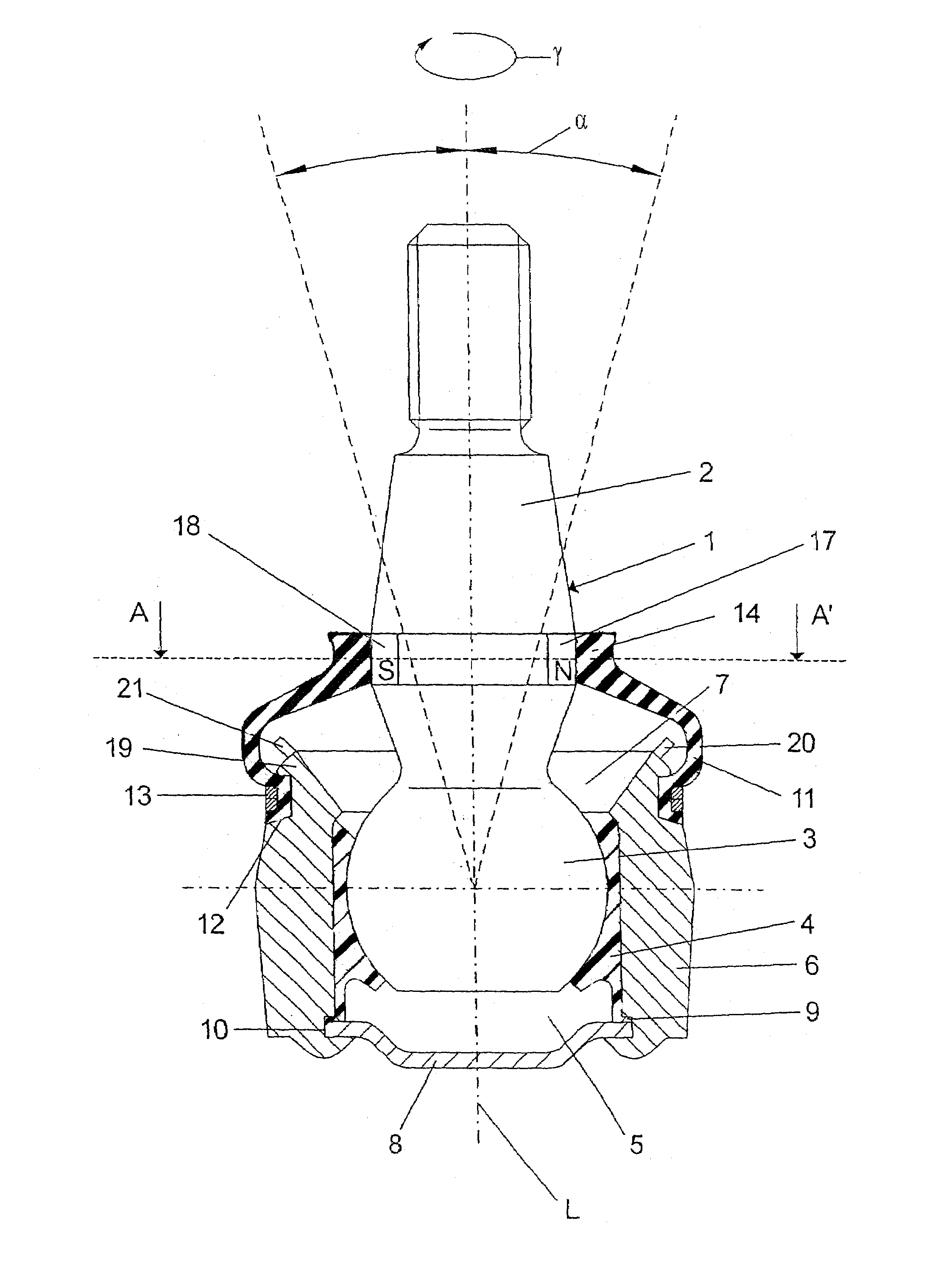
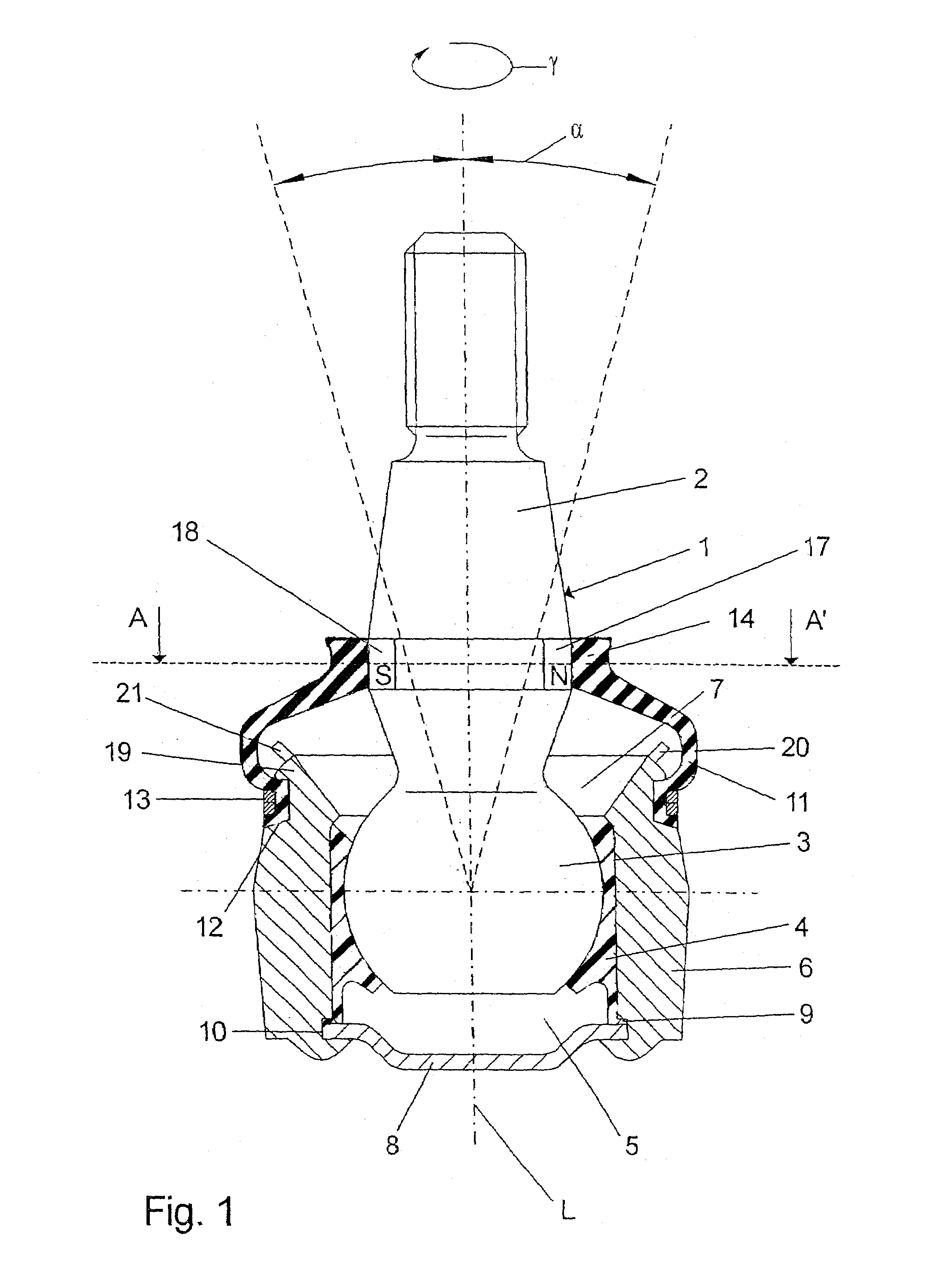
[0028]Referring to the drawings in particular, FIG. 1 shows an embodiment of the ball and socket joint according to the present invention, in which a ball pivot 1 with a pin 2 and a joint ball 3 is rotatably and pivotably mounted in a recess 5 in a housing 6 through the intermediary of a bearing shell 4. The ball pivot 1 extends, with its pin 2, through an opening 7 provided in the housing 6 out of this housing 6, whereby the housing 6 is closed via a cover 8 at one end opposite the opening 7. The cover 8 meshes, together with a radial projection 9 of the bearing shell 4, with an annular groove 10 provided in the housing 6, such that the cover 8 and the bearing shell 4 are fixed at the housing 6 in a positive-locking manner.

[0029]Between the housing 6 and the pin 2 is arranged a sealing bellows 11, which, with its housing-side end, is enclosed in a groove 12 provided in the housing 6 and is held via clamping rings 13. On its pin-side end, the sealing bellows 11 has a sealing area 14...


PUM


Abstract

A ball joint for a motor vehicle includes a housing (6) having a cavity (5), and with a ball pivot (1), which has a pin (2) and a joint ball (3) and which, with its joint ball (3), is mounted in the cavity (5) of the housing (6) in a manner that permits it to rotate and pivot. The journal (2) extends through an opening (7) provided in the housing and out therefrom. The inventive ball joint also comprises sealing bellows (11), which are placed between the housing (6) and the journal (2). A multipart measuring arrangement is provided having at least one signal transmitter (17, 18) and at least one sensor (20, 21, 22). The measuring arrangement is placed between the pin-side end of the joint ball (3) and the pin-side end of the sealing bellows (11).

Description

CROSS REFERENCE TO RELATED APPLICATIONS[0001]This application is a United States National Phase application of International Application PCT / DE2004 / 002190 filed Oct. 1, 2004 and claims the benefit of priority under 35 U.S.C. 119 of German Patent Application DE 10350640 filed Oct. 29, 2003, the entire contents of which are incorporated herein by reference.FIELD OF THE INVENTION[0002]The present invention pertains to a ball and socket joint for a motor vehicle, with a housing having a recess, a ball pivot which has a pin and a joint ball which is mounted with its joint ball rotatably and pivotably in the recess of the housing, whereby the pin extends out through an opening provided in the housing, a sealing bellows arranged between the housing and the pin and with a multipart measuring array, which has at least one signal transmitter and at least one sensor.BACKGROUND OF THE INVENTION[0003]Chassis data regarding steering angle as well as load state and spring deflection state are curr...

Claims


Application Information

Patent Timeline
Patent Type & Authority Patents(United States)
IPC IPC(8): G01M17/06G01M99/00B60G17/019B62D7/16B62D15/02F16C11/06
CPCB60G17/019F16C11/0671B62D15/021F16C11/0619B62D7/166B60G2204/11B60G2204/416F16C41/007F16C11/0604F16C11/0633F16C2326/01F16C2326/24F16C2326/05F16C11/06B62D7/00B62D15/02B62D7/16
Inventor GRABER, JURGENSPRATTE, JOACHIM
Owner ZF FRIEDRICHSHAFEN AG
Why Eureka
Try Eureka